


880MHz low-noise amplifier application circuit composed of RF2347
#RF2347
#low-noise amplifier
#880MHz
#RF signal
#amplifier circuit
#radio frequency
#signal processing
#wireless communication
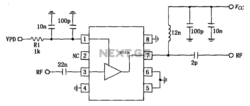
Description: The circuit is based on an 880 MHz RF2347 low noise amplifier application. The radio frequency (RF) signal enters through input pin 3, and after amplification, the output is available at pin 7. The amplifier is directly coupled to pin 3, with an additional 22 pF blocking coupling capacitance. Impedance matching is designed for operation at 836 MHz with a typical impedance of 50 ohms. Pin 7 serves as an open collector output terminal, which can be connected to the power supply (Vcc) through a choke or matching inductor. The output impedance matching network is external and ensures maximum output power and efficiency. Pin 1 functions as the power down control terminal for bias management. When VPD is set to 2.8 V (±0.1 V), the typical current (IPD) is 8.5 mA; when VPD is at 0.9 V, the circuit shuts down. An additional RF bypass circuit is required for proper operation.
The RF2347 low noise amplifier circuit operates effectively at a frequency of 880 MHz, making it suitable for various RF applications. The design incorporates a direct coupling mechanism from the input pin (pin 3) to the amplifier, allowing for minimal signal degradation. The use of a 22 pF blocking capacitor ensures that DC components do not interfere with the RF signal, thereby preserving the integrity of the amplified output.
The output stage, located at pin 7, is configured as an open collector, enabling flexibility in connecting to different power supply configurations through a choke or matching inductor. This design choice allows for efficient impedance matching, which is critical for maximizing output power and overall circuit efficiency. The external output matching network is crucial in aligning the amplifier's output impedance to the standard 50 ohms, facilitating optimal power transfer to subsequent stages or antennas.
Pin 1 serves a dual purpose as the power down control terminal, providing a means to manage the biasing of the amplifier. The circuit is designed to operate at a nominal voltage of 2.8 V, drawing a typical current of 8.5 mA, which indicates the active state of the amplifier. Conversely, when the voltage at VPD drops to 0.9 V, the amplifier enters a low-power state, effectively shutting down to conserve energy. An additional RF bypass circuit is recommended to stabilize the operation of the amplifier during transitions between active and inactive states, ensuring reliable performance across varying conditions. Overall, this low noise amplifier design is well-suited for applications requiring high gain and low noise performance in the RF spectrum. As shown in FIG constituted by 880MHz RF2347 low noise amplifier application circuit. Radio frequency (RF) signal from the input pin 3, after the output of the amplifier 7 feet . 3 feet and the internal amplifier is directly coupled, so 3 feet plus a 22pF blocking coupling capacitance, impedance matching at 836MHz work as 50. 7 feet for the open collector output terminal can be connected to the power supply Vcc through choke or matching inductor, the pin impedance matching is typically 50, external output matching network allows the amplifier output impedance matching for maximum output power and efficiency.
1 foot for the power down control terminal for controlling bias. When VPD (2.8 0.1) V when (IPD is typically 8.5mA) circuit; when VPD 0.9V circuit closes; VPD requested additional RF bypass circuit.
The RF2347 low noise amplifier circuit operates effectively at a frequency of 880 MHz, making it suitable for various RF applications. The design incorporates a direct coupling mechanism from the input pin (pin 3) to the amplifier, allowing for minimal signal degradation. The use of a 22 pF blocking capacitor ensures that DC components do not interfere with the RF signal, thereby preserving the integrity of the amplified output.
The output stage, located at pin 7, is configured as an open collector, enabling flexibility in connecting to different power supply configurations through a choke or matching inductor. This design choice allows for efficient impedance matching, which is critical for maximizing output power and overall circuit efficiency. The external output matching network is crucial in aligning the amplifier's output impedance to the standard 50 ohms, facilitating optimal power transfer to subsequent stages or antennas.
Pin 1 serves a dual purpose as the power down control terminal, providing a means to manage the biasing of the amplifier. The circuit is designed to operate at a nominal voltage of 2.8 V, drawing a typical current of 8.5 mA, which indicates the active state of the amplifier. Conversely, when the voltage at VPD drops to 0.9 V, the amplifier enters a low-power state, effectively shutting down to conserve energy. An additional RF bypass circuit is recommended to stabilize the operation of the amplifier during transitions between active and inactive states, ensuring reliable performance across varying conditions. Overall, this low noise amplifier design is well-suited for applications requiring high gain and low noise performance in the RF spectrum. As shown in FIG constituted by 880MHz RF2347 low noise amplifier application circuit. Radio frequency (RF) signal from the input pin 3, after the output of the amplifier 7 feet . 3 feet and the internal amplifier is directly coupled, so 3 feet plus a 22pF blocking coupling capacitance, impedance matching at 836MHz work as 50. 7 feet for the open collector output terminal can be connected to the power supply Vcc through choke or matching inductor, the pin impedance matching is typically 50, external output matching network allows the amplifier output impedance matching for maximum output power and efficiency.
1 foot for the power down control terminal for controlling bias. When VPD (2.8 0.1) V when (IPD is typically 8.5mA) circuit; when VPD 0.9V circuit closes; VPD requested additional RF bypass circuit.
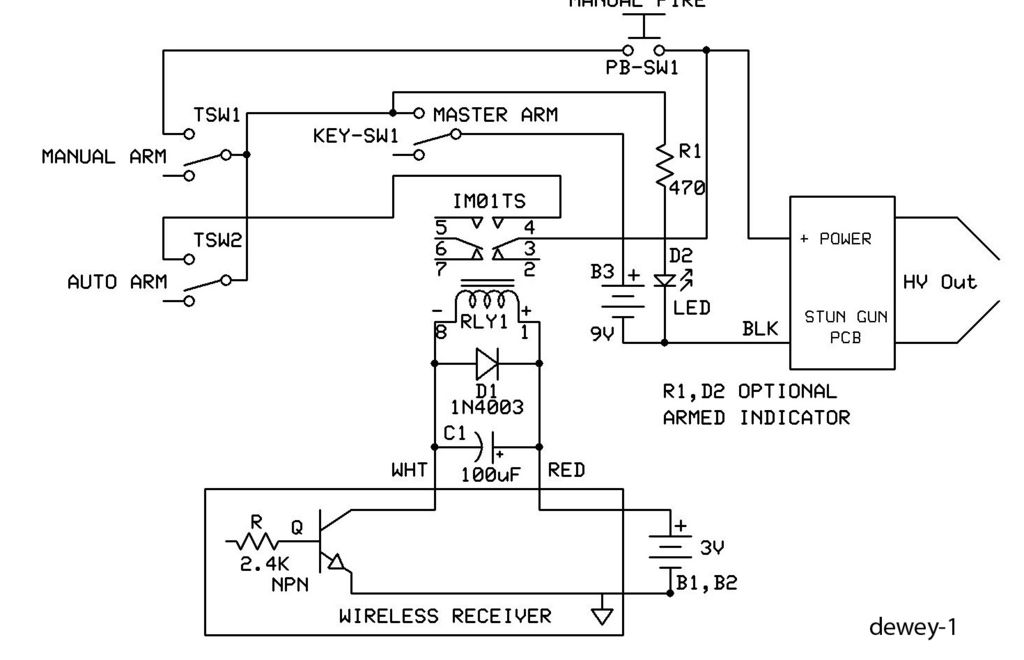
Remote Ignition System 100kv StunGun
This is a straightforward guide on creating an economical remote or wireless ignition system for a spud gun or similar applications. It employs a doorbell circuit to transmit a radio frequency (RF) signal to activate a relay, which completes a...
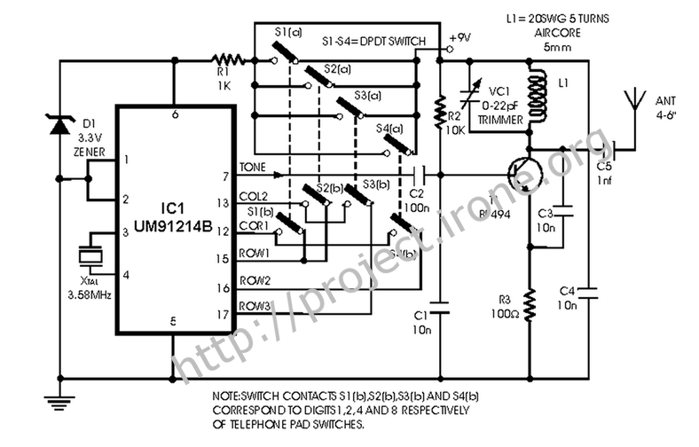
Radio frequency Of Remote Control
This is a remote control circuit that uses radio frequency electrical signals to control a variety of applications. Component: Transistor.
The remote control circuit operates by transmitting radio frequency (RF) signals to communicate with various devices. At its core, the circuit...
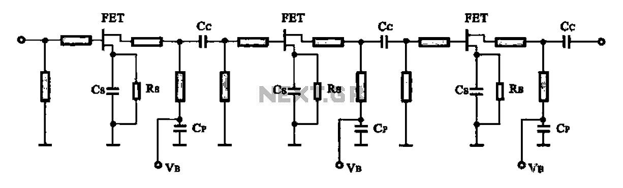
Low-noise amplifier
In general high-frequency circuits within the microwave band, microstrip circuits are utilized to achieve input and output matching as well as frequency-selective amplifier circuits. A figure illustrates a monolithic microwave integrated circuit low-noise amplifier. Additionally, a downconverter mixer includes a...
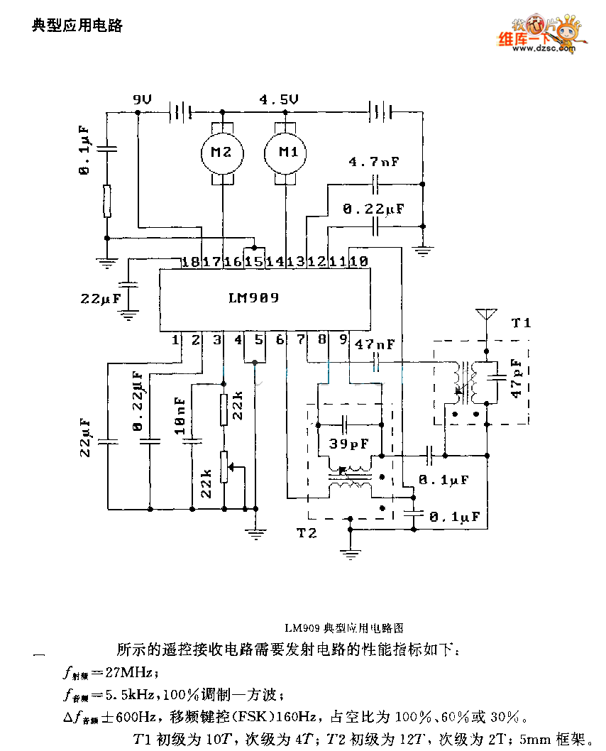
LM909 radio telecontrol receiving decoding circuit diagram
The performance indices of the telecontrol receiving decoding circuit are as follows: radio frequency (f) = 27 MHz, audio frequency (f) = 5.5 kHz, 100% modulation in square-wave form; radio frequency deviation is ±600 Hz, and the frequency shift keying...

METAL DETECTOR
When the receiver is tuned to a medium wave radio station, feedback howl caused by the transmitter may occur when the coil and radio are positioned above or near a metal object. The search head is constructed from a margarine...
remote control for electrical
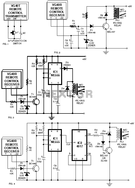
A circuit for a remote control unit utilizes radio frequency signals to operate various electrical appliances. This remote control unit features four channels, which can be expanded to twelve. Unlike typical remote control circuits that rely on infrared light for...
bugs
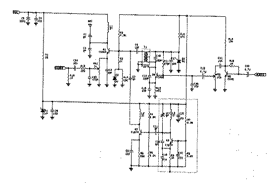
Radio transmitters for eavesdropping on private conversations and sending video pictures, battery-operated.
Radio transmitters designed for eavesdropping applications typically operate within specific frequency ranges to capture audio and video signals discreetly. These devices often utilize low-power RF (radio frequency) technology to...
Plastic Pipe Finder
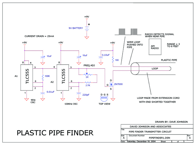
This circuit is designed to track the location of a plastic pipe buried underground. It transmits a weak RF signal that can be detected by a portable AM radio from a distance of approximately 6 feet.
The circuit operates by generating...
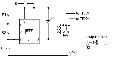
Oscillator circuit schematic
This webpage outlines the radio transmitter unit that was part of the Cirrus One rocket mission in April 2001. The transmitter was included as a payload due to concerns about recovery challenges if the rocket drifted far downrange after reaching...