


A frequency multiplier in depth
#frequency multiplier
#PLL
#phase locked loop
#RF
#signal processing
#integer frequency
#circuit design
#electronics
#frequency doubling
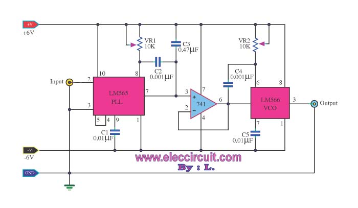
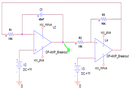
Description: Most frequency multiplier circuits utilize an integrated circuit (IC) phase-locked loop (PLL). These circuits typically increase the frequency by an integer factor only. However, this particular circuit is capable of doubling the frequency.
Frequency multiplier circuits are essential in various applications where signal frequency needs to be increased for better performance or functionality. The phase-locked loop (PLL) is a fundamental component in these circuits, as it synchronizes the output frequency to a reference frequency input.
In this specific frequency doubling circuit, the PLL is configured to achieve a multiplication factor of two. The core components include a voltage-controlled oscillator (VCO), a phase comparator, and a loop filter. The VCO generates a frequency that is controlled by the input signal. The phase comparator compares the phase of the input signal with the VCO output and generates an error signal that drives the loop filter. The loop filter smooths this error signal to provide a stable control voltage to the VCO, ensuring that the output frequency is precisely double that of the input frequency.
The circuit design may also incorporate additional features such as frequency stability enhancements, noise reduction techniques, and output buffering to ensure the doubled frequency signal maintains integrity across various loads and conditions. Proper layout considerations, including minimizing parasitic capacitance and inductance, are crucial in achieving optimal performance in high-frequency applications.
This frequency doubling circuit using a PLL is widely applicable in communication systems, RF transmission, and signal processing where precise frequency control is paramount.Most of the frequency multiplier circuit using IC phase locked loop (PLL).It will increase the frequency to an integer only. But this circuit can double the..
Frequency multiplier circuits are essential in various applications where signal frequency needs to be increased for better performance or functionality. The phase-locked loop (PLL) is a fundamental component in these circuits, as it synchronizes the output frequency to a reference frequency input.
In this specific frequency doubling circuit, the PLL is configured to achieve a multiplication factor of two. The core components include a voltage-controlled oscillator (VCO), a phase comparator, and a loop filter. The VCO generates a frequency that is controlled by the input signal. The phase comparator compares the phase of the input signal with the VCO output and generates an error signal that drives the loop filter. The loop filter smooths this error signal to provide a stable control voltage to the VCO, ensuring that the output frequency is precisely double that of the input frequency.
The circuit design may also incorporate additional features such as frequency stability enhancements, noise reduction techniques, and output buffering to ensure the doubled frequency signal maintains integrity across various loads and conditions. Proper layout considerations, including minimizing parasitic capacitance and inductance, are crucial in achieving optimal performance in high-frequency applications.
This frequency doubling circuit using a PLL is widely applicable in communication systems, RF transmission, and signal processing where precise frequency control is paramount.Most of the frequency multiplier circuit using IC phase locked loop (PLL).It will increase the frequency to an integer only. But this circuit can double the..

precision phase locked loop circuit
The precision Phase Locked Loop (PLL) in this circuit operates similarly to a basic PLL, but with several enhancements. The flip-flops in the detector are equipped with a gate G1 to clear them, allowing for a faster response. The currents...
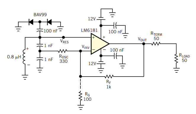
RF oscillator uses current-feedback op amp
A current-feedback amplifier is a well-known component with many uses. Its basic block diagram shows that its input stage is a voltage follower in practice, a symmetrical emitter follower. The configuration samples the output current, converts it to voltage across...
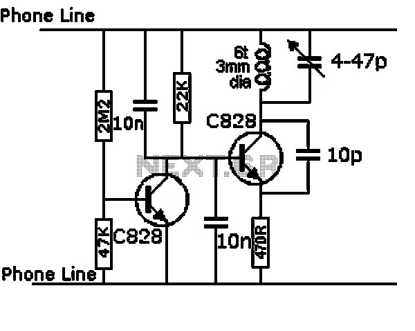
pll fm demodulator
This circuit is a Phase-Locked Loop (PLL) system designed to function as an FM demodulator. The output of the Voltage-Controlled Oscillator (VCO) tracks the FM signal, and since the input voltage of the VCO is proportional to its output frequency,...
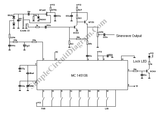
PLL Oscillator for Medium Wave Frequency
A PLL oscillator, or phase-locked loop oscillator, is a control method that compares a controlled system or plant to a reference signal.
A phase-locked loop (PLL) oscillator is a sophisticated electronic circuit designed to synchronize an output signal's phase and frequency...
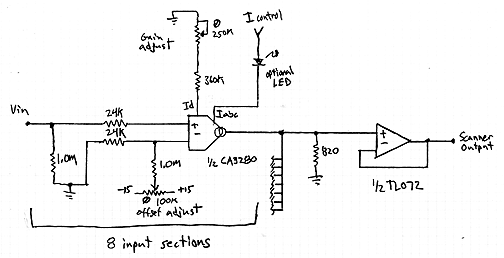
Interpolating Scanner Circuit
This design is for an interpolating scanner, a circuit featuring multiple signal inputs, a control voltage input, and a signal output. The output selectively transitions between inputs, smoothly fading from one to the next as the control voltage increases. A...
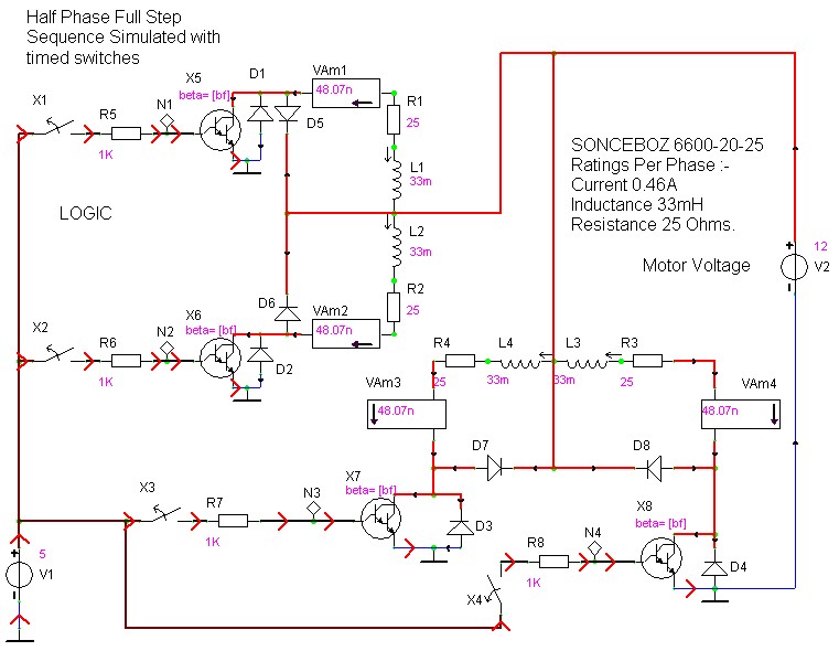
case stepper
Beige Bag Software has been offering affordable and innovative circuit design tools since 1990. B2 Spice provides schematics as well as analog, digital, and mixed-mode electronic circuit simulation. It integrates with EAGLE and CADSTAR PCB software.
B2 Spice is a powerful...
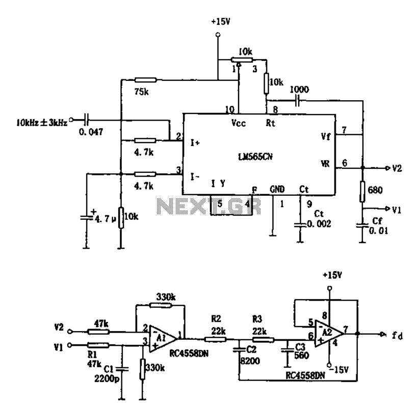
PLL FM demodulator LM565CN RC4558DN schematic
The circuit utilizes a 10 kHz and 3 kHz LM565CN to create an FM demodulation setup. The output diagram (b) illustrates the differential demodulation outputs V1 and V2 from the differential amplifier A1, which provides level displacement and amplification. Subsequently,...
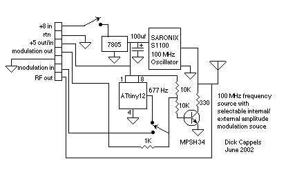
100 MHz RF oscillator with ATtiny12
A frequency reference for tuning up the RS-232 to 100 MHz RF desktop channel adapter elsewhere on this site, when I found this Saronix crystal oscillator in my junk box. A few minutes with AVRStudio produced an ATtiny12 to make...
Jammer circuit
The frequency jammer operates by generating interfering RF noise centered around a 2.45 GHz carrier frequency. As the power of this noise increases, the signal-to-noise ratio of the wireless communication channel decreases, leading to a higher bit error rate until...