


A Push-Pull Hartley VFO transmitter
#Hartley VFO
#transmitter
#oscillator
#electron coupled oscillator
#RF
#filament-type tubes
#Dow's ECO
#screen grounded
#filament chokes
#variation circuit
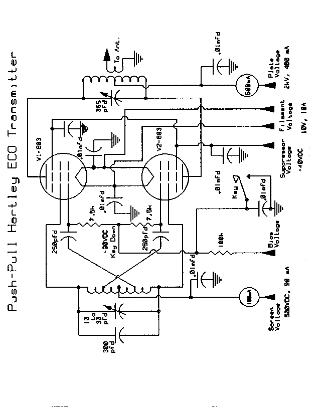
Description: This is a variation of the Electron Coupled Oscillator (ECO) circuit, pioneered by Dow in 1931. Dow's ECO has the screen grounded for RF. In this circuit, filament-type tubes are used instead of heater-cathode types, eliminating the need for filament chokes in this initial attempt. The cathodes are utilized as the grounded or common electrode. It is anticipated that this circuit functions similarly to the standard ECO: the cathode, grid, and screen comprise the oscillator section, with the screen acting as the oscillator's plate. The tube's plate and its associated tuned circuit form the amplifier section of the transmitter. Essentially, this configuration allows two tubes to perform the work of four. The circuit employs grid-block keying, and all components, except for the tuned circuit component values, are depicted on the schematic. The plate voltage should be approximately 1500 VDC, the screen voltage should range between 300 and 500 VDC, the suppressor voltage should be around 40 VDC, and the bias (blocking bias) should be about -150 VDC. The power input should not exceed 150 watts. Adjustments to voltages and loading are necessary for optimal keying. A push-pull grid/parallel plate (push-push) circuit may offer improved stability and eliminate parasitics or the need for neutralization, as suggested by a member of the GB list. The plate circuit would then be tuned to twice the frequency of the grid circuit. Caution is advised when applying screen voltage; it should never be applied before the plate voltage when using tetrodes or pentodes, as this could result in the screens failing dramatically. This circuit is designed to effectively feed a good antenna coupler.
The Electron Coupled Oscillator circuit described utilizes two filament-type tubes configured in a manner that leverages their inherent properties to create an efficient oscillator and amplifier system. The choice of using cathodes as the common electrode is significant, as it simplifies the design by removing the need for filament chokes, which can introduce additional complexity and potential points of failure.
In this configuration, the oscillator section is formed by the interaction of the cathode, grid, and screen. The screen's role as the oscillator's plate is crucial, as it allows for the generation of oscillations that can be amplified by the tube's plate circuit. The tuned circuit associated with the plate is designed to maximize the amplification of the oscillations produced, ensuring that the transmitter operates effectively.
The circuit parameters, including the specified voltages for the plate, screen, suppressor, and bias, are critical for the proper functioning of the oscillator and amplifier. The recommended plate voltage of 1500 VDC and screen voltage range of 300 to 500 VDC are indicative of high-power RF applications, while the suppressor voltage and bias settings ensure that the tubes operate within their safe limits, preventing damage and ensuring reliability.
The suggestion to consider a push-pull configuration further enhances the potential for stability and performance. By tuning the plate circuit to twice the frequency of the grid circuit, the design can mitigate issues related to parasitic oscillations, which are a common challenge in high-frequency RF circuits. This approach not only improves the overall stability of the oscillator but also enhances the quality of the output signal.
In summary, this variation of the Electron Coupled Oscillator circuit represents a thoughtful adaptation of established principles in RF circuit design, with specific attention to component selection and configuration aimed at optimizing performance while ensuring operational safety. The circuit's design is well-suited for experimentation and further refinement, particularly in the context of amateur radio and high-frequency applications.This is a variation of the the Electron Coupled Oscillator circuit, pioneered by Dow in 1931. Dow`s ECO has the screen "grounded" for RF. In this circuit, because I am using filament-type tubes instead of heater-cathode types, and because I didn`t want to build or use a pair of filament chokes with this first attempt, I chose to use the "cathodes" as the "grounded" or "common" electrode. I am hoping that it otherwise works much the same way as the standard ECO: i. e. , the cathode-grid-screen are the oscillator section, with the screen acting as the oscillator`s plate, and the plate of the tube and its associated tuned circuit making up the amplifier section of the transmitter. So, essentially, we have two tubes performing the work of four. Should be interesting. This circuit uses grid-block keying, and all components, with the exception of the values of tuned circuit components, are shown on the schematic.
Plate voltage should be about 1500 VDC, screen voltage should be 300 - 500 VDC, suppressor voltage should be about 40 VDC, and bias (actually blocking bias) should be about -150 VDC. Power input should not exceed about 150 watts. Adjust voltages and loading for best keying. It might be better to use a push-pull grid/parallel plate (push-push) circuit, as suggested by one of the members of the GB list.
The plate circuit would then be tuned to twice the grid circuit frequency. This should provide much better stability, and eliminate any parasitics or need for neutralization. Experimentation is in order. For any of these oscillator circuits which use tetrodes or pentodes, be sure to never apply screen voltage before applying plate voltage. Otherwise the screens may disappear in a blinding flash of light. This circuit should feed a good antenna coupler.
The Electron Coupled Oscillator circuit described utilizes two filament-type tubes configured in a manner that leverages their inherent properties to create an efficient oscillator and amplifier system. The choice of using cathodes as the common electrode is significant, as it simplifies the design by removing the need for filament chokes, which can introduce additional complexity and potential points of failure.
In this configuration, the oscillator section is formed by the interaction of the cathode, grid, and screen. The screen's role as the oscillator's plate is crucial, as it allows for the generation of oscillations that can be amplified by the tube's plate circuit. The tuned circuit associated with the plate is designed to maximize the amplification of the oscillations produced, ensuring that the transmitter operates effectively.
The circuit parameters, including the specified voltages for the plate, screen, suppressor, and bias, are critical for the proper functioning of the oscillator and amplifier. The recommended plate voltage of 1500 VDC and screen voltage range of 300 to 500 VDC are indicative of high-power RF applications, while the suppressor voltage and bias settings ensure that the tubes operate within their safe limits, preventing damage and ensuring reliability.
The suggestion to consider a push-pull configuration further enhances the potential for stability and performance. By tuning the plate circuit to twice the frequency of the grid circuit, the design can mitigate issues related to parasitic oscillations, which are a common challenge in high-frequency RF circuits. This approach not only improves the overall stability of the oscillator but also enhances the quality of the output signal.
In summary, this variation of the Electron Coupled Oscillator circuit represents a thoughtful adaptation of established principles in RF circuit design, with specific attention to component selection and configuration aimed at optimizing performance while ensuring operational safety. The circuit's design is well-suited for experimentation and further refinement, particularly in the context of amateur radio and high-frequency applications.This is a variation of the the Electron Coupled Oscillator circuit, pioneered by Dow in 1931. Dow`s ECO has the screen "grounded" for RF. In this circuit, because I am using filament-type tubes instead of heater-cathode types, and because I didn`t want to build or use a pair of filament chokes with this first attempt, I chose to use the "cathodes" as the "grounded" or "common" electrode. I am hoping that it otherwise works much the same way as the standard ECO: i. e. , the cathode-grid-screen are the oscillator section, with the screen acting as the oscillator`s plate, and the plate of the tube and its associated tuned circuit making up the amplifier section of the transmitter. So, essentially, we have two tubes performing the work of four. Should be interesting. This circuit uses grid-block keying, and all components, with the exception of the values of tuned circuit components, are shown on the schematic.
Plate voltage should be about 1500 VDC, screen voltage should be 300 - 500 VDC, suppressor voltage should be about 40 VDC, and bias (actually blocking bias) should be about -150 VDC. Power input should not exceed about 150 watts. Adjust voltages and loading for best keying. It might be better to use a push-pull grid/parallel plate (push-push) circuit, as suggested by one of the members of the GB list.
The plate circuit would then be tuned to twice the grid circuit frequency. This should provide much better stability, and eliminate any parasitics or need for neutralization. Experimentation is in order. For any of these oscillator circuits which use tetrodes or pentodes, be sure to never apply screen voltage before applying plate voltage. Otherwise the screens may disappear in a blinding flash of light. This circuit should feed a good antenna coupler.
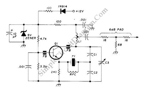
90-125 Mhz Crystal RF Oscillator
This circuit operates at a frequency range of 90-125 MHz and is particularly useful for VHF/UHF converters. It provides an output power of 5 to 15 mW. The circuit can utilize high-quality fifth- or seventh-over-tone crystal types. A ferrite bead...
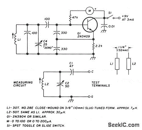
LC CHECKER
The circuit operates on the principle of the grid-dip or absorption effect, which takes place when a parallel resonant circuit is coupled to an oscillator operating at the same frequency. Transistor Q1 functions within a standard Colpitts oscillator circuit, maintaining...
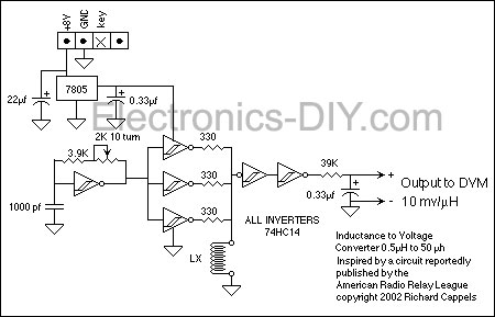
RF Inductance Meter
This RF inductance meter measures RF chokes in the 500 nH to 50 µH range. A simple solution was required to measure hand-wound RF inductors in a secondary lab setting. The user intended to utilize this device occasionally and did...
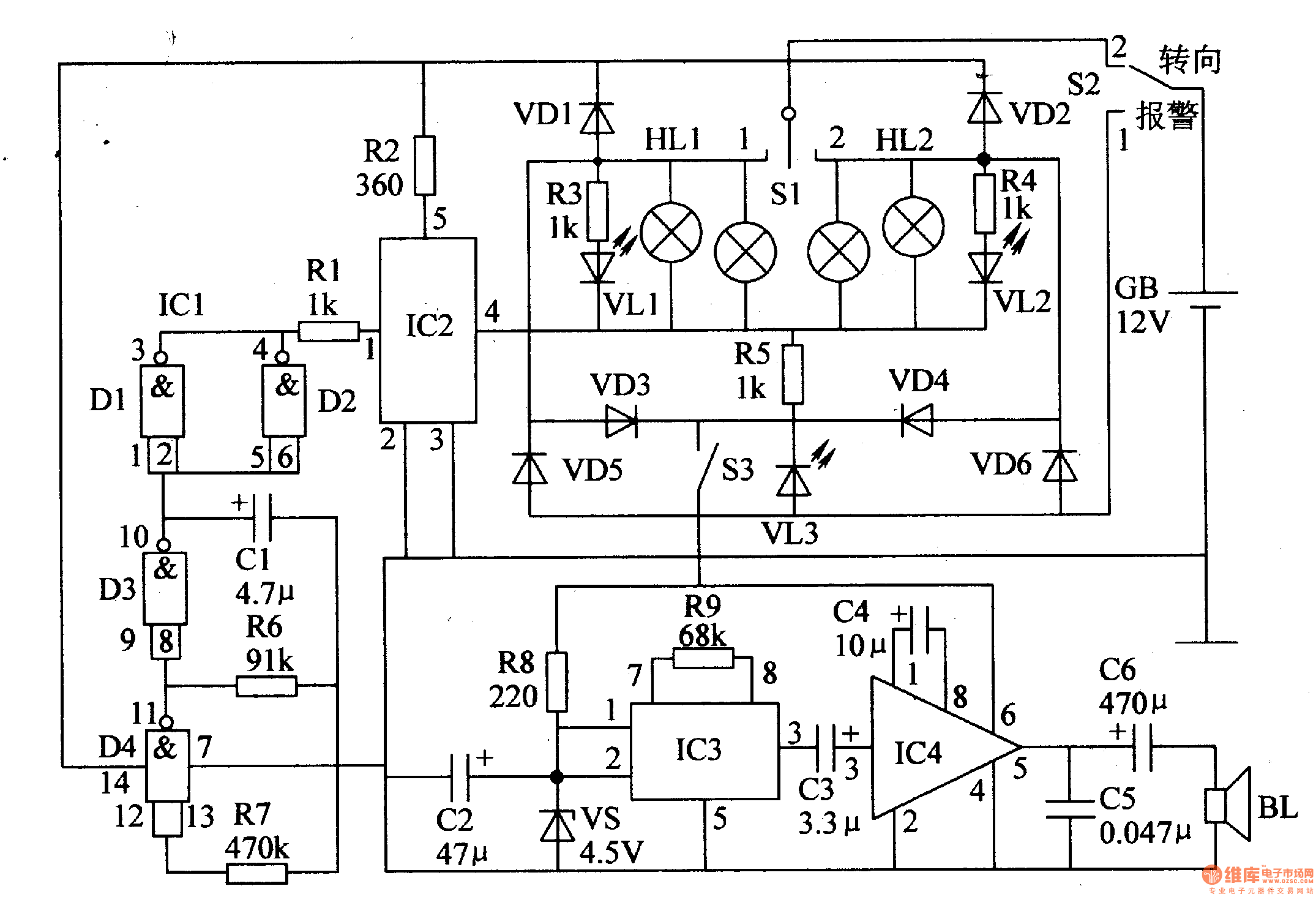
Auto Flash Alarm - Staircase_Control
The circuit comprises a low-frequency oscillator, an electronic switch circuit, a control circuit, a photoelectric display circuit, and a music alarm circuit. The low-frequency oscillator is constructed using an integrated circuit (IC) with internal NAND gates and external resistor-capacitor (RC)...
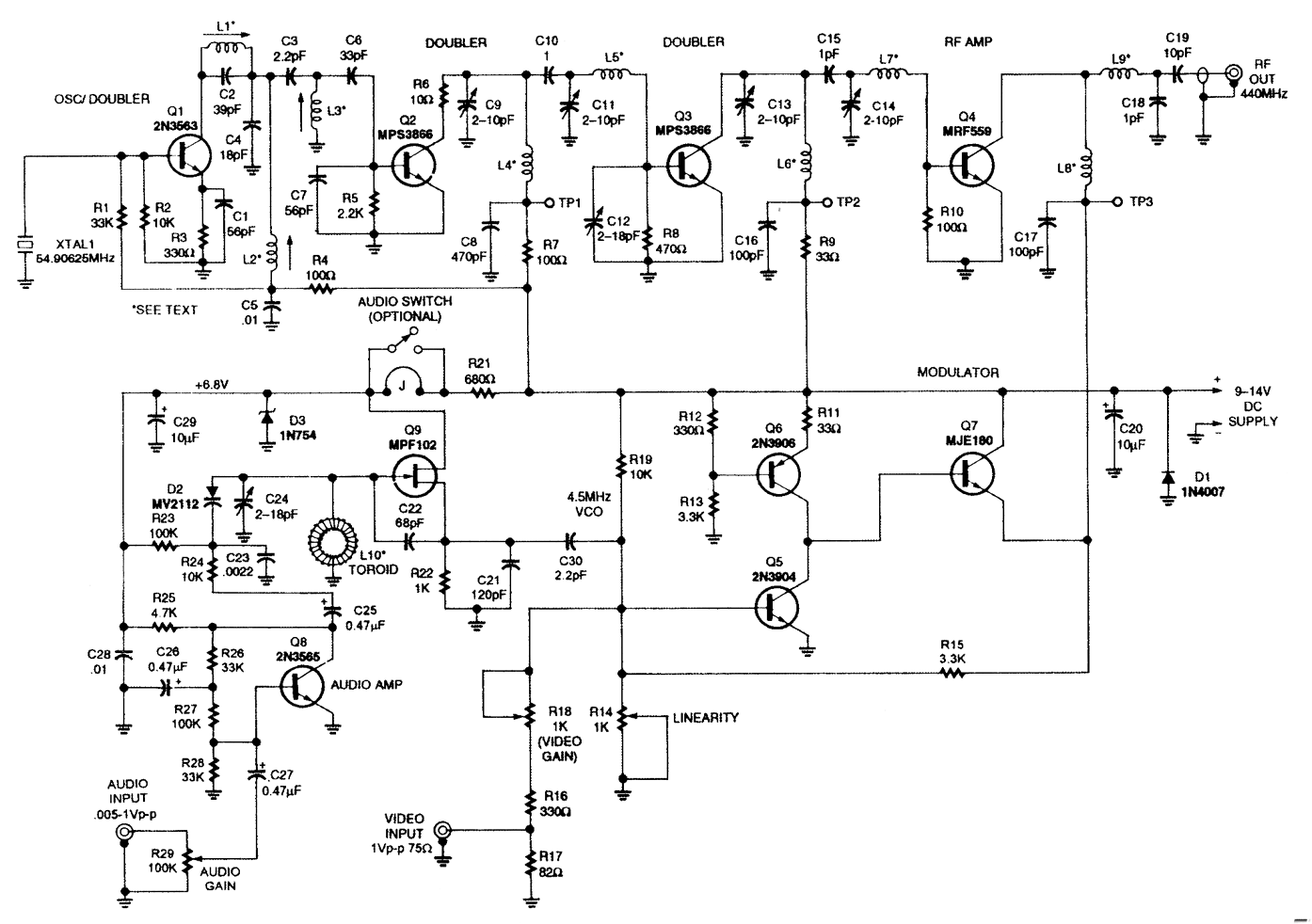
MINI_ATV_TRANSMITTER
This low-power NTSC video and sound transmitter is suitable for amateur radio, video handheld transceivers, remote control applications, and surveillance purposes. It features a crystal oscillator-multiplier and a power amplifier. Video modulation is achieved through a three-transistor series modulator. The...
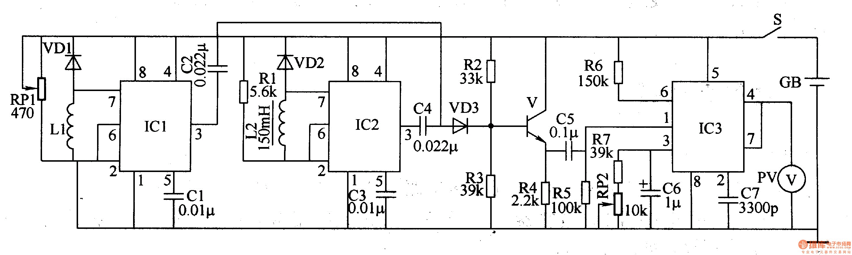
Metal detector 4
The metal detector circuit comprises a detection oscillator, a reference oscillator, a mixer, and a signal display, as illustrated in Figure 8-70. The detection oscillator circuit is made up of the time base oscillator IC1, inductor L1, potentiometer RP1, diode...
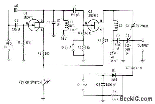
14W CW TRANSMITTER
A low-power two-stage FET transmitter designed for the 80-meter amateur band utilizes a Pierce crystal oscillator that does not require an output resonant circuit. A DC milliammeter can be connected across a 150-ohm resistor in the gate circuit of the...
14W CW TRANSMITTER
A low-power two-stage FET transmitter designed for the 80-meter amateur band utilizes a Pierce crystal oscillator that does not require an output resonant circuit. A DC milliammeter can be connected across a 150-ohm resistor in the gate circuit of the...
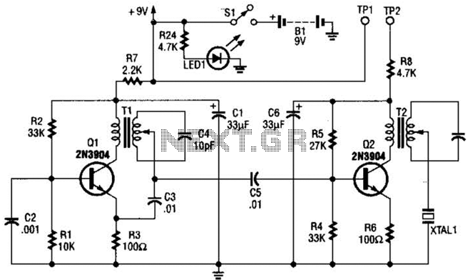
20M Cw Transmitter Circuit
The transmitter features a VXO circuit that drives a keyed amplifier. This keyed amplifier powers an MRF 476 final amplifier, producing approximately 2 watts of output. Additionally, a solid-state T-R switch is incorporated for the receiver. The component values provided...