


Active Antenna for 10 to 30 MHz
#active antenna
#signal amplifier
#transistor
#BF256C
#BF494
#10-30 MHz
#RF amplifier
#transformer
#frequency range
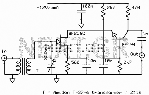
Description: The schematic shown is a 2 transistor signal amplifier between 10 MHz to 30 MHz. The BF256C and the BF494 are very popular transistors and are easy to find. The transformer works as insulator and amplifier. That circuit can give 20 dB gain. The variable capacitor is for exact tuning at the favorite radio station. The circuit can be powered by a 9 to 12V power supply and because the current consumption is too small like 5mA you can use batteries.
The described circuit is a two-transistor signal amplifier designed for operation within the frequency range of 10 MHz to 30 MHz. It utilizes the BF256C and BF494 transistors, both of which are well-known for their availability and performance in RF applications. The circuit achieves a gain of approximately 20 dB, making it suitable for amplifying weak radio signals for clearer reception.
The configuration incorporates a transformer, which serves a dual purpose: it acts as an insulator to prevent DC signals from affecting the input and output stages, and it also contributes to the amplification of the RF signal. This transformer is crucial in ensuring that the circuit can effectively couple signals while maintaining isolation between different stages and minimizing signal loss.
A variable capacitor is included in the design, allowing for fine-tuning of the circuit to optimize reception of the desired radio station. This tuning capability is essential for enhancing selectivity and ensuring that the amplifier can effectively filter out unwanted frequencies.
Power supply requirements for the circuit are flexible, accommodating a range of 9 to 12 volts. The low current consumption of approximately 5 mA makes this circuit particularly suitable for battery operation, enhancing its portability and ease of use in various applications, including portable radio receivers and other RF signal processing devices.
Overall, the design is straightforward yet effective, making it an ideal choice for hobbyists and professionals looking to build a reliable RF amplifier.The schematic shown, is a 2 transistor signal amplifier between 10 MHz to 30 MHz. The BF256C and the BF494 are very popular transistors and are easy to find. The transformer works as insulator and amplifier. http://www.next.gr/rf/antennas/active-antennas/ That circuit can give 20 dB gain. The variable capacitor is for exact tuning at the favorite radio station. The circuit can be powered by a 9 to 12V power supply and because the current consumption is too small like 5mA you can use batteries.
The described circuit is a two-transistor signal amplifier designed for operation within the frequency range of 10 MHz to 30 MHz. It utilizes the BF256C and BF494 transistors, both of which are well-known for their availability and performance in RF applications. The circuit achieves a gain of approximately 20 dB, making it suitable for amplifying weak radio signals for clearer reception.
The configuration incorporates a transformer, which serves a dual purpose: it acts as an insulator to prevent DC signals from affecting the input and output stages, and it also contributes to the amplification of the RF signal. This transformer is crucial in ensuring that the circuit can effectively couple signals while maintaining isolation between different stages and minimizing signal loss.
A variable capacitor is included in the design, allowing for fine-tuning of the circuit to optimize reception of the desired radio station. This tuning capability is essential for enhancing selectivity and ensuring that the amplifier can effectively filter out unwanted frequencies.
Power supply requirements for the circuit are flexible, accommodating a range of 9 to 12 volts. The low current consumption of approximately 5 mA makes this circuit particularly suitable for battery operation, enhancing its portability and ease of use in various applications, including portable radio receivers and other RF signal processing devices.
Overall, the design is straightforward yet effective, making it an ideal choice for hobbyists and professionals looking to build a reliable RF amplifier.The schematic shown, is a 2 transistor signal amplifier between 10 MHz to 30 MHz. The BF256C and the BF494 are very popular transistors and are easy to find. The transformer works as insulator and amplifier. http://www.next.gr/rf/antennas/active-antennas/ That circuit can give 20 dB gain. The variable capacitor is for exact tuning at the favorite radio station. The circuit can be powered by a 9 to 12V power supply and because the current consumption is too small like 5mA you can use batteries.
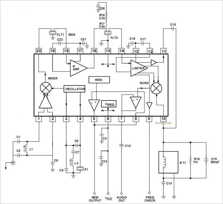
SA608 SA608 Low Voltage High Performance Mixer FM IF System
The SA9614 is an RF amplifier utilized for signal conversion and automatic laser power control (ALPC) between the CD optical pickup head and the decoding chip. The SA9614 incorporates an interface for the CD optical diode RF signal amplifier and...
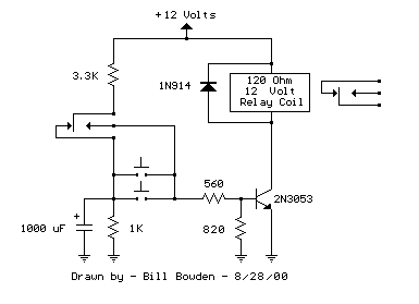
1 Transistor Toggle Relay schematic
The circuit below requires a double pole, double throw relay in conjunction with a single transistor to allow toggling the relay with a momentary push button. One set of relay contacts is used to control the load, while the other...
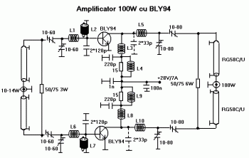
100W RF Amplifier Circuit With BLY94 Transistor
This is a component of a 100W RF amplifier. This circuit is constructed using the RF power transistor BLY94. Components include the BLY94 transistor, inductor, and others.
The 100W RF amplifier circuit utilizing the BLY94 transistor is designed to amplify radio...

2W RF Amplifier with MOSFET LF2810A
This is a 2W RF amplifier circuit built with the power MOSFET LF2810A. The schematic of the microstrip single-stage RF amplifier is shown in Figure A. The amplifier utilizes the M/A-Com LF2810A MOSFET, which is rated for a power output...
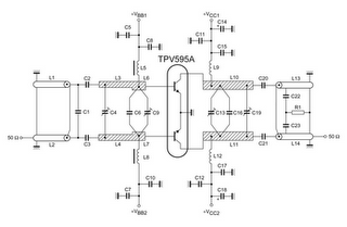
tv power amplifier schematic
TV RF Power Amplifier 14W. This RF power amplifier operates within the frequency range of 470 - 860 MHz, covering UHF Band IV and V, and delivers an output power of 14 Watts with an input power of 1.5 Watts....
Audio operated relay
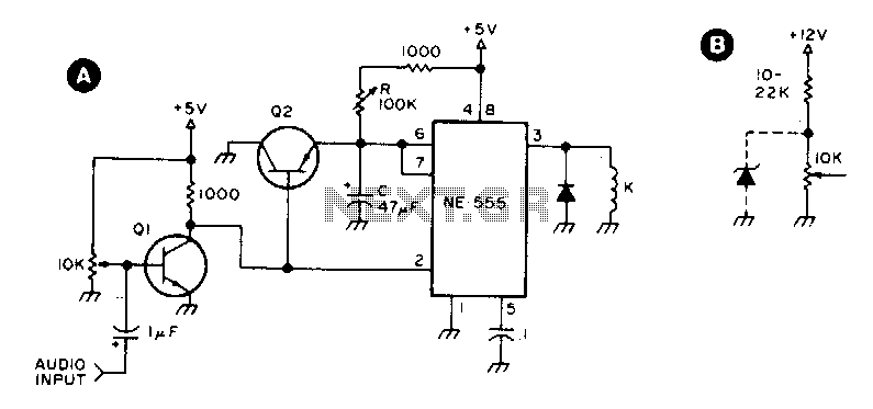
Q1 and Q2 are general-purpose transistors. The 10 kΩ input potentiometer is adjusted to a point just short of where Q1 turns on, as indicated by relay K engaging. K is any 5 V reed relay. With the specified values...
600W rf power amplifier
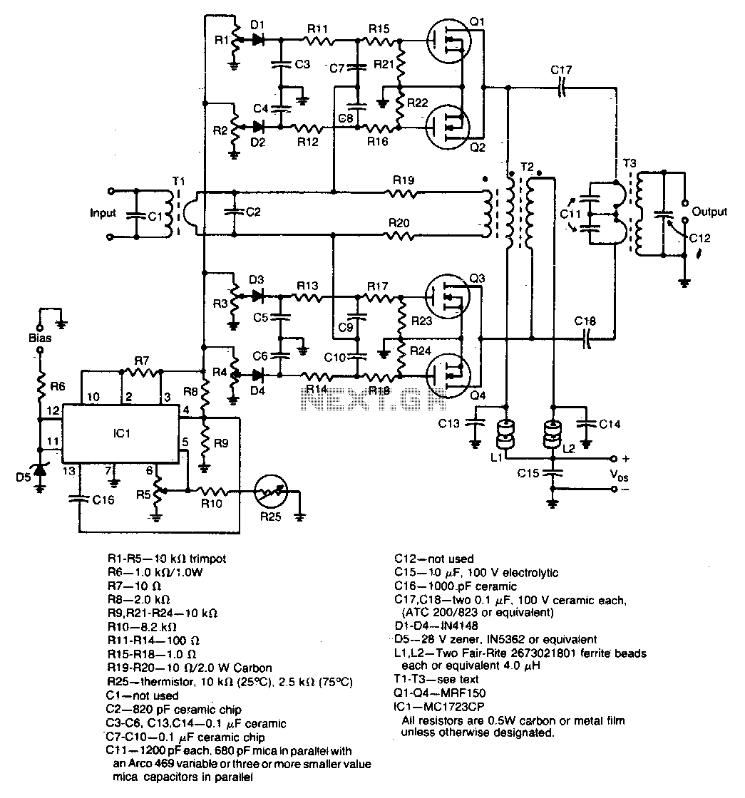
A unique push-pull parallel circuit utilizes four MRF150 RF power FETs connected in parallel at relatively high power levels. Supply voltages ranging from 40 to 50 Vdc can be employed, contingent on the linearity requirements. The bias for each device...
Astable Multivibrator with 2 Transistors
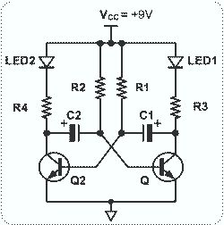
This circuit is straightforward and easy to construct, utilizing two transistors as active components along with several passive components such as resistors, capacitors, and two LEDs. The circuit employs the MPS2222 transistor, though any NPN type transistor can be used...
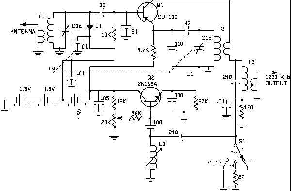
Regency ATC-1 Converter
The 1956 Regency ATC-1 converter marked the beginning of a new era in amateur radio. This compact converter utilized only two transistors—one PNP and one NPN—both made of germanium and now considered obsolete. However, they represented the onset of a...