


AM circuit ring
#AM circuit
#diode ring
#modulator
#RF
#discrete circuits
#resistive element
#signal processing
#communication
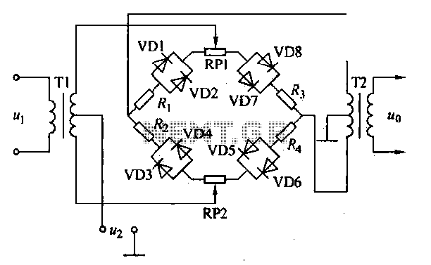
Description: An AM diode ring circuit consists of four diodes arranged in a ring configuration, commonly referred to as a diode ring modulator circuit. This circuit offers significant advantages due to the characteristics of the diodes and the use of discrete components. It often requires the incorporation of resistive element correction circuits. In practical applications, the diode used in the annular AM circuit is typically the VD 2AP9. Reference values for other device parameters include resistances: Ri = R2 = Ra = R4 = 100Ω and RRPI = Rr = PZ = 470Ω. The diode ring circuit facilitates low-frequency modulation signals and high-frequency carrier signals, converting them into an output signal Qi via a high-frequency amplitude modulation circuit. The amplitude modulation circuit features a simple structure, produces minimal harmonic output, and exhibits good balance and symmetry, making it a popular choice for implementation in integrated circuits.
The AM diode ring modulator circuit operates by utilizing four diodes configured in a circular arrangement, which enables effective mixing of the input signals. Each diode in the ring contributes to the modulation process, allowing for the combination of low-frequency audio signals with high-frequency carrier waves. The diodes are essential in shaping the output waveform, ensuring that the amplitude of the carrier signal is altered according to the amplitude of the modulating signal.
The specified diode model, 2AP9, is selected for its favorable characteristics in terms of forward voltage drop and switching speed, making it suitable for high-frequency applications. The resistive components, with values of 100Ω and 470Ω, serve to stabilize the circuit and optimize performance by providing necessary biasing and load conditions. These resistors help to ensure that the diodes operate within their optimal range, minimizing distortion and enhancing the fidelity of the output signal.
The output signal Qi produced by the circuit is a modulated waveform that retains the information of the original audio signal while being transmitted at a higher frequency. The design's simplicity is advantageous, as it reduces the complexity of the circuit and the potential for errors during assembly. Additionally, the low harmonic output contributes to a cleaner signal, which is crucial in communication systems where clarity is paramount.
This diode ring modulator circuit is often integrated into larger systems, such as radio transmission and reception modules, where compactness and efficiency are essential. Its balanced and symmetrical output characteristics make it an ideal candidate for integration into ICs, allowing for mass production and reliability in various electronic applications.AM diode ring circuit consists of four diodes to form a ring road, so called diode ring modulator circuit. AM diode ring circuits greater advantages. Due to the characteristics of the diode and discrete circuits, etc., often have to use resistive element correction circuit, the circuit shown
in actual annular AM diode VD are 2AP9. Other device parameters reference values: resistance; Ri = R2 = Ra = R4 -l OOtl, RRPI -Rr {PZ-470fl. Diode ring circuit low-frequency modulation signal amplitude and high frequency carrier signal by the high-frequency amplitude modulation circuit converting the signal output Qi. The amplitude modulation circuit is simple structure, less harmonic output, good balance and symmetry, often used in the form of an integrated circuit.
The AM diode ring modulator circuit operates by utilizing four diodes configured in a circular arrangement, which enables effective mixing of the input signals. Each diode in the ring contributes to the modulation process, allowing for the combination of low-frequency audio signals with high-frequency carrier waves. The diodes are essential in shaping the output waveform, ensuring that the amplitude of the carrier signal is altered according to the amplitude of the modulating signal.
The specified diode model, 2AP9, is selected for its favorable characteristics in terms of forward voltage drop and switching speed, making it suitable for high-frequency applications. The resistive components, with values of 100Ω and 470Ω, serve to stabilize the circuit and optimize performance by providing necessary biasing and load conditions. These resistors help to ensure that the diodes operate within their optimal range, minimizing distortion and enhancing the fidelity of the output signal.
The output signal Qi produced by the circuit is a modulated waveform that retains the information of the original audio signal while being transmitted at a higher frequency. The design's simplicity is advantageous, as it reduces the complexity of the circuit and the potential for errors during assembly. Additionally, the low harmonic output contributes to a cleaner signal, which is crucial in communication systems where clarity is paramount.
This diode ring modulator circuit is often integrated into larger systems, such as radio transmission and reception modules, where compactness and efficiency are essential. Its balanced and symmetrical output characteristics make it an ideal candidate for integration into ICs, allowing for mass production and reliability in various electronic applications.AM diode ring circuit consists of four diodes to form a ring road, so called diode ring modulator circuit. AM diode ring circuits greater advantages. Due to the characteristics of the diode and discrete circuits, etc., often have to use resistive element correction circuit, the circuit shown
in actual annular AM diode VD are 2AP9. Other device parameters reference values: resistance; Ri = R2 = Ra = R4 -l OOtl, RRPI -Rr {PZ-470fl. Diode ring circuit low-frequency modulation signal amplitude and high frequency carrier signal by the high-frequency amplitude modulation circuit converting the signal output Qi. The amplitude modulation circuit is simple structure, less harmonic output, good balance and symmetry, often used in the form of an integrated circuit.
Interpolating Scanner Circuit
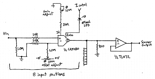
This design is for an interpolating scanner, a circuit featuring multiple signal inputs, a control voltage input, and a signal output. The output selectively transitions between inputs, smoothly fading from one to the next as the control voltage increases. A...
Radio harmonic detection circuit
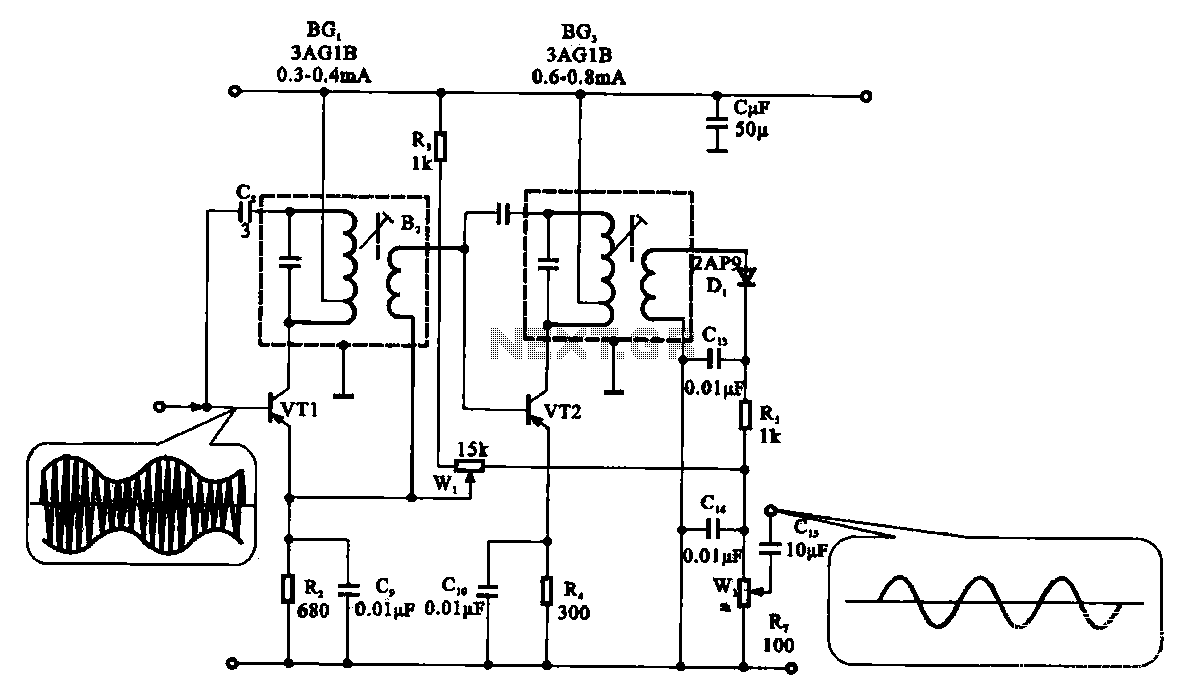
The demodulation and detection circuit is a radio AM intermediate frequency (IF) signal amplifier that performs two-stage detection using diode Dr. It extracts the audio signal from the IF carrier detection and subsequently sends it to the power amplifier stage....
Visual modulation indicator
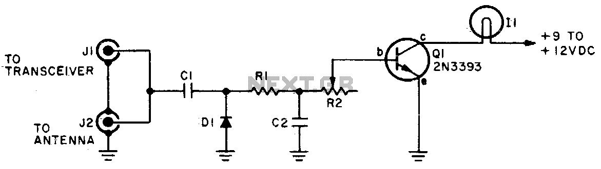
The brightness of the indicator lamp changes in accordance with the modulated RF signal. Adjust resistor R2 while the transmitter is on (modulated) until the lamp flashes in sync with the modulation.
Cl = 5 pF, C2 = 100 pF, Dl...
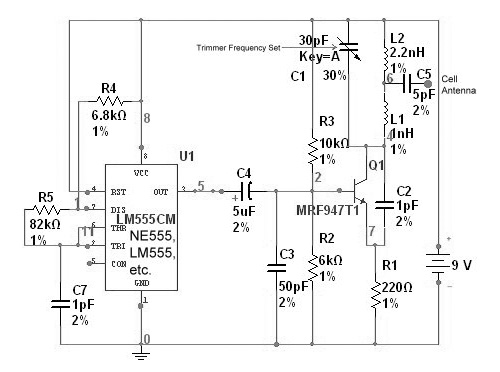
radio station blocker circuit
This device functions as a reversal of a radio station, sending a null signal to a selected frequency to eliminate the actual broadcast. The radio transmitter operates at a loss of 10,000W; therefore, this circuit is intended for use only...
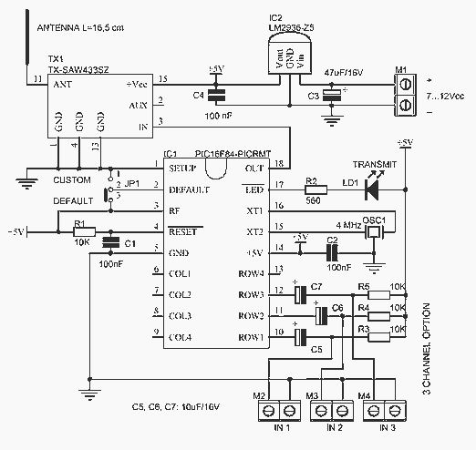
RF wireless allarm magnetic switch PIC16F84
This circuit was formed to create a wireless alarm from a normal magnetic contact. By fixing the magnet to the leaf of a door, or swing of a drawer, it is easy to reveal the opening. To transmit the signal...
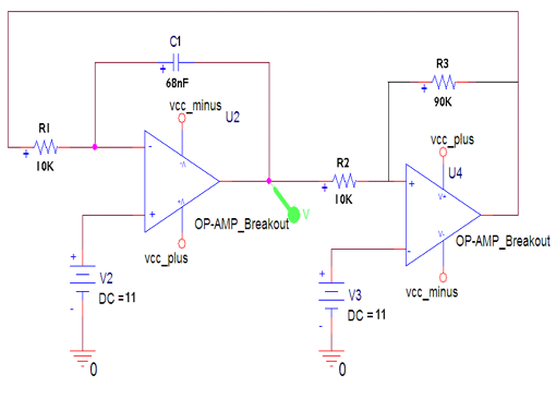
Jammer circuit
The frequency jammer operates by generating interfering RF noise centered around a 2.45 GHz carrier frequency. As the power of this noise increases, the signal-to-noise ratio of the wireless communication channel decreases, leading to a higher bit error rate until...
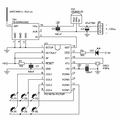
6 Channel RF Remote Control
This project creates a simple but valuable wireless remote controller. It has as many as 6 channels (a rare feature for remote control devices) and transmits encoded MM53200, UM3750, or UM86409. Of course, you can omit the button and make...
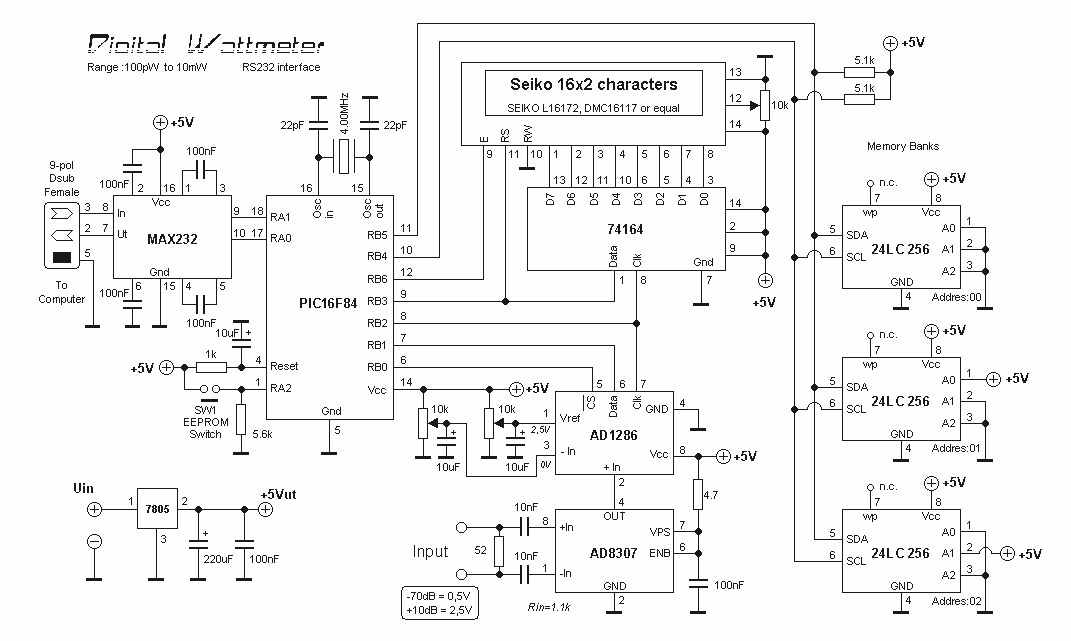
RF Digital Wattmeter
The power is measured by the circuit AD8307 over a 50 ohm dummy load. An A/D converter of 12 bit converts the analog output from the AD8307 to a digital number. Since the AD is a 12 bit A/D, you...
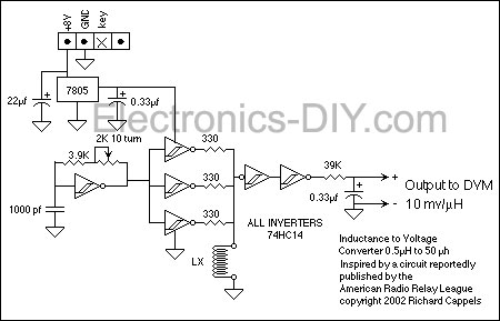
RF Inductance Meter
This RF inductance meter measures RF chokes in the 500 nH to 50 µH range. A simple solution was required to measure hand-wound RF inductors in a secondary lab setting. The user intended to utilize this device occasionally and did...