


am radio circuit using transistor
#AM transmitter
#transistor
#ceramic resonator
#3.587 MHz
#RF circuit
#radio frequency
#filter
#resonator
#frequency modulation
#wireless transmission
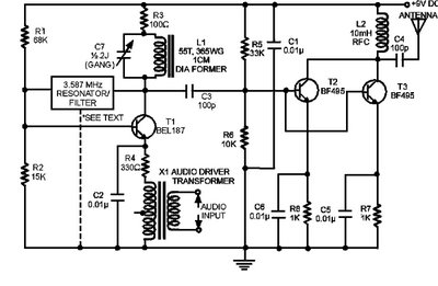
Description: The circuit presented here is a powerful AM transmitter utilizing a ceramic resonator/filter operating at 3.587 MHz. This circuit primarily relies on a transistor for its core functionality. It is possible to use resonators/filters of other frequencies, such as 5.5 MHz, 7 MHz, and 10.7 MHz, although this will require corresponding adjustments to the value of the inductor in the tank circuit of the oscillator connected to the collector of transistor T1. The audio frequency (AF) input for modulation is introduced in series with the emitter of transistor T1 (along with resistor R4) using a transistor radio-type audio driver transformer, as depicted in the circuit. The modulated RF output is generated across the tank circuit, which can be tuned to the resonant frequency of the filter/resonator with the aid of gang condenser C7. The subsequent two stages, constructed using low-noise RF transistors BF495, are connected in parallel to amplify the modulated signal that is coupled from the collector of transistor T1 to the bases of transistors T2 and T3. The combined output from the collectors of T2 and T3 is transmitted to the antenna through a 100pF capacitor C4. This circuit can be efficiently assembled on a general-purpose PCB, and the expected range of the transmitter is between one to two kilometers. A regulated 9-volt power supply is required for the circuit's operation. Note: The dotted line indicates an additional connection if a 3-pin filter is used instead.
The AM transmitter circuit is designed to operate at a frequency of 3.587 MHz, making it suitable for medium-wave broadcasting. The core of the circuit employs a transistor (T1), which functions as the oscillator and modulator. The use of a ceramic resonator ensures frequency stability and precision, which is crucial for AM transmission. When utilizing resonators of different frequencies, the inductor value in the tank circuit must be recalibrated to maintain the desired resonance.
The modulation process is achieved by injecting an audio signal into the emitter of T1. The inclusion of resistor R4 is essential for biasing, ensuring the transistor operates within its active region. The audio driver transformer facilitates the coupling of the audio signal to the RF circuit, allowing for effective modulation of the carrier wave.
The tank circuit, composed of the inductor and the ceramic resonator, plays a vital role in determining the frequency of oscillation. The gang condenser (C7) allows for fine-tuning of the circuit, enabling the user to adjust the output to the exact resonant frequency for optimal transmission performance.
Following the initial modulation stage, the circuit employs two BF495 transistors (T2 and T3) configured in parallel to amplify the modulated signal. This configuration enhances the overall gain of the transmitter, ensuring that the output signal is strong enough for effective transmission. The output from these transistors is then coupled to the antenna via a 100pF capacitor (C4), which blocks any DC component while allowing the RF signal to pass through.
The design of the circuit permits easy assembly on a general-purpose PCB, making it accessible for hobbyists and engineers alike. The anticipated range of one to two kilometers is suitable for various applications, including personal broadcasting and experimental radio projects. The requirement for a regulated 9-volt power supply ensures consistent performance and reliability, critical for maintaining signal integrity during operation.
In summary, this AM transmitter circuit is a robust solution for medium-wave broadcasting, featuring adjustable frequency capabilities and efficient amplification stages, making it a valuable project for electronics enthusiasts.The circuit for a powerful AM transmitter using ceramic resonator/filter of 3. 587 MHz is presented here. This circuit is based on transistor for the core operation of the circuit. Resonators/filters of other frequencies such as 5. 5 MHz, 7 MHz and 10. 7 MHz may also be used. Use of different frequency filters/resonators will involve corresponding va riation in the value of inductor used in the tank circuit of oscillator connected at the collector of transistor T1. This is the figure of the circuit; The AF input for modulation is inserted in series with emitter of transistor T1 (and resistor R4) using a transistor radio type audio driver transformer as shown in the circuit.
Modulated RF output is developed across the tank circuit which can be tuned to resonance frequency of the filter/resonator with the help of gang condenser C7. The next two stages formed using low-noise RF transistors BF495 are, in fact, connected in parallel for amplification of modulated signal coupled from collector of transistor T1 to bases of transistors T2 and T3.
The combined output from collectors of T2 and T3 is fed to antenna via 100pF capacitor C4. The circuit can be easily assembled on a general-purpose PCB. The range of the transmitter is expected to be one to two kilometers. The circuit requires regulated 9 volt power supply for its operation. Note: Dotted lined indicates additional connection if a 3-pin filter is used in place.
The AM transmitter circuit is designed to operate at a frequency of 3.587 MHz, making it suitable for medium-wave broadcasting. The core of the circuit employs a transistor (T1), which functions as the oscillator and modulator. The use of a ceramic resonator ensures frequency stability and precision, which is crucial for AM transmission. When utilizing resonators of different frequencies, the inductor value in the tank circuit must be recalibrated to maintain the desired resonance.
The modulation process is achieved by injecting an audio signal into the emitter of T1. The inclusion of resistor R4 is essential for biasing, ensuring the transistor operates within its active region. The audio driver transformer facilitates the coupling of the audio signal to the RF circuit, allowing for effective modulation of the carrier wave.
The tank circuit, composed of the inductor and the ceramic resonator, plays a vital role in determining the frequency of oscillation. The gang condenser (C7) allows for fine-tuning of the circuit, enabling the user to adjust the output to the exact resonant frequency for optimal transmission performance.
Following the initial modulation stage, the circuit employs two BF495 transistors (T2 and T3) configured in parallel to amplify the modulated signal. This configuration enhances the overall gain of the transmitter, ensuring that the output signal is strong enough for effective transmission. The output from these transistors is then coupled to the antenna via a 100pF capacitor (C4), which blocks any DC component while allowing the RF signal to pass through.
The design of the circuit permits easy assembly on a general-purpose PCB, making it accessible for hobbyists and engineers alike. The anticipated range of one to two kilometers is suitable for various applications, including personal broadcasting and experimental radio projects. The requirement for a regulated 9-volt power supply ensures consistent performance and reliability, critical for maintaining signal integrity during operation.
In summary, this AM transmitter circuit is a robust solution for medium-wave broadcasting, featuring adjustable frequency capabilities and efficient amplification stages, making it a valuable project for electronics enthusiasts.The circuit for a powerful AM transmitter using ceramic resonator/filter of 3. 587 MHz is presented here. This circuit is based on transistor for the core operation of the circuit. Resonators/filters of other frequencies such as 5. 5 MHz, 7 MHz and 10. 7 MHz may also be used. Use of different frequency filters/resonators will involve corresponding va riation in the value of inductor used in the tank circuit of oscillator connected at the collector of transistor T1. This is the figure of the circuit; The AF input for modulation is inserted in series with emitter of transistor T1 (and resistor R4) using a transistor radio type audio driver transformer as shown in the circuit.
Modulated RF output is developed across the tank circuit which can be tuned to resonance frequency of the filter/resonator with the help of gang condenser C7. The next two stages formed using low-noise RF transistors BF495 are, in fact, connected in parallel for amplification of modulated signal coupled from collector of transistor T1 to bases of transistors T2 and T3.
The combined output from collectors of T2 and T3 is fed to antenna via 100pF capacitor C4. The circuit can be easily assembled on a general-purpose PCB. The range of the transmitter is expected to be one to two kilometers. The circuit requires regulated 9 volt power supply for its operation. Note: Dotted lined indicates additional connection if a 3-pin filter is used in place.
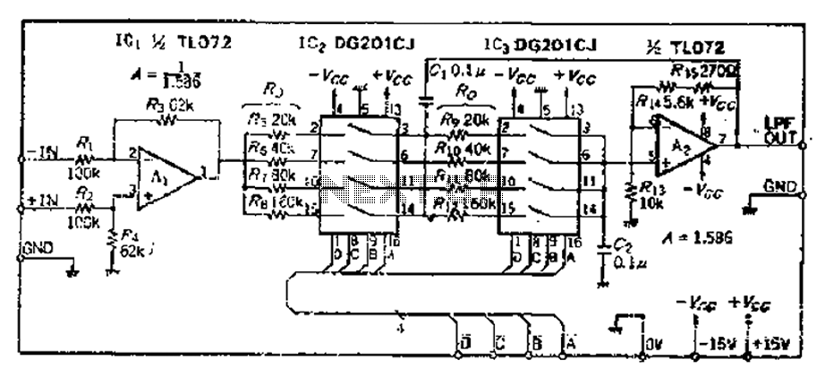
By setting the cutoff frequency of the programmable digital low-pass filter
The circuit primarily consists of two Butterworth filters, designed to create a feedback amplifier with a gain of approximately 0.707. It features a differential input amplifier, where one input is grounded, resulting in a single input terminal. The attenuation filter...
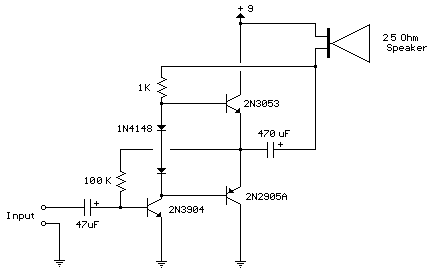
improved 3 transistor audio amp
This circuit is similar to the previous one but employs positive feedback to enhance the amplitude delivered to the speaker. It is adapted from a small 5-transistor radio that utilizes a 25-ohm speaker. In the earlier circuit, the load resistor...
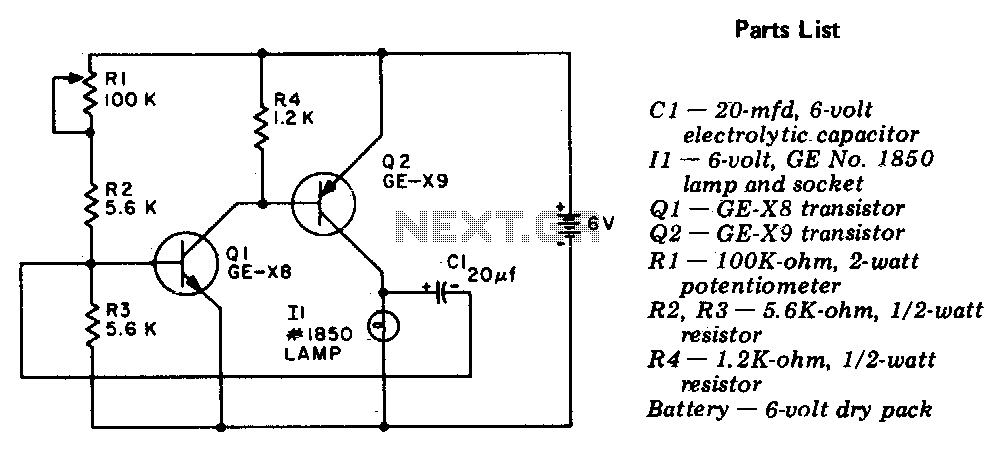
Flasher-light control
The circuit is a two-stage, direct-coupled transistor amplifier configured as a free-running multivibrator. Both the flash duration and flash interval can be adjusted by turning the potentiometer, R1.
The described circuit operates as a two-stage, direct-coupled transistor amplifier, functioning as a...
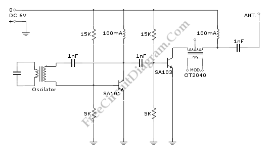
2 Transistors Mini MW Transmitter
This is a Mini MW (Medium Wave) Transmitter circuit. This circuit consists of a combination of transistors SA103 and SA101. These transistors are used as oscillators.
The Mini MW Transmitter circuit is designed to operate in the medium wave band, typically...
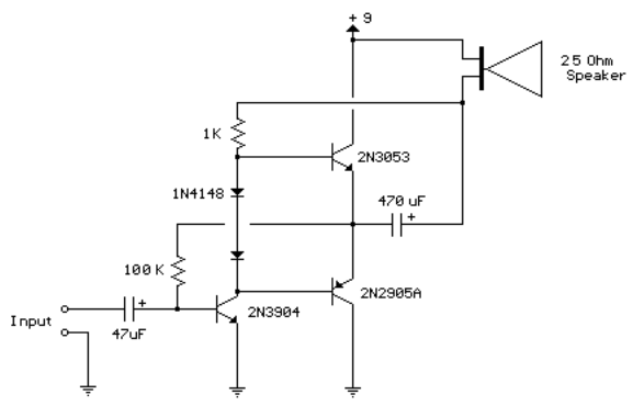
3 transistor audio amp 80 milliwatt
This circuit is similar to the previous one but employs positive feedback to enhance the amplitude delivered to the speaker. It was derived from a small 5-transistor radio utilizing a 25-ohm speaker. In the previous circuit, the load resistor for...
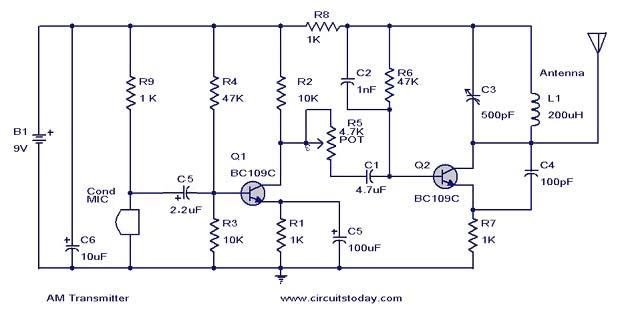
am transmitter circuit
This document presents a circuit diagram of a simple AM transmitter that is capable of transmitting audio signals to a specified area. The circuit is designed with a limited power output to comply with FCC regulations while effectively producing sufficient...
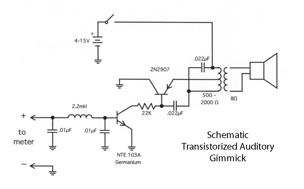
Transistorized Auditory Gimmick
This circuit first appeared in "The Braille Technical Press," edited by Robert W. Gunderson, in 1955. Gunderson, W2JIO, designed this "gimmick" to read transmitter meters. It has appeared many times over a 20-year period, including in commercial aids and appliances...
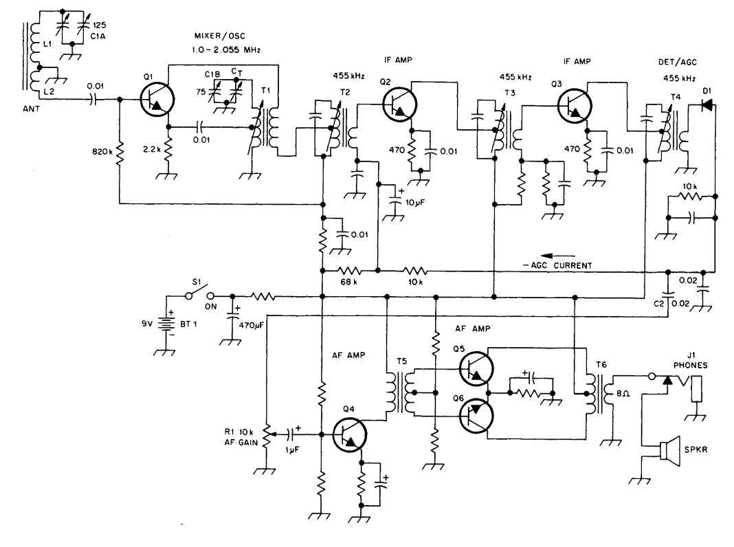
TRANSISTORIZED AM RADIO
The schematic illustrates a standard AM radio circuit utilizing NPN transistors. This generic circuit does not provide specific values for all components, serving instead as a reference point for experimenters to begin their projects.
The schematic of a typical transistor AM...

Easy Build Motorcycle Alarm
The following circuit is a simple, inexpensive, and easy-to-build motorcycle alarm. The circuit requires only two transistors to drive a relay, which acts as a switch to activate a buzzer. Any number of normally-open switches can be used. Mercury switches...