


autodyne 1

Description: Autodyne is a term used to describe a heterodyne radio device where a single tube functions simultaneously as both an oscillator and a detector.
The autodyne radio circuit is a specialized design that combines the functions of signal generation and detection within a single active component, typically a vacuum tube or a transistor. In this configuration, the oscillator generates a radio frequency (RF) signal that is mixed with the incoming radio signal. The resulting heterodyning process produces intermediate frequencies (IF) that can be easily processed.
In a basic autodyne circuit, the oscillator's frequency is slightly offset from the frequency of the incoming signal. This offset creates a beat frequency, which is the difference between the two frequencies. The tube's dual functionality allows for efficient signal processing, as it eliminates the need for separate oscillator and detector stages, thereby simplifying the overall design and reducing component count.
The design typically includes a tuned circuit, which is crucial for selecting the desired frequency and ensuring stability. The output of the circuit can be further filtered and amplified to improve signal quality. The autodyne configuration is particularly advantageous in applications where space and power efficiency are critical, such as in portable radio receivers.
Overall, the autodyne radio device exemplifies a compact and efficient approach to radio signal processing, leveraging the capabilities of a single active component to achieve both oscillation and detection.autodyne n. A heterodyne radio device in which one tube serves simultaneously as oscillator and detector..
The autodyne radio circuit is a specialized design that combines the functions of signal generation and detection within a single active component, typically a vacuum tube or a transistor. In this configuration, the oscillator generates a radio frequency (RF) signal that is mixed with the incoming radio signal. The resulting heterodyning process produces intermediate frequencies (IF) that can be easily processed.
In a basic autodyne circuit, the oscillator's frequency is slightly offset from the frequency of the incoming signal. This offset creates a beat frequency, which is the difference between the two frequencies. The tube's dual functionality allows for efficient signal processing, as it eliminates the need for separate oscillator and detector stages, thereby simplifying the overall design and reducing component count.
The design typically includes a tuned circuit, which is crucial for selecting the desired frequency and ensuring stability. The output of the circuit can be further filtered and amplified to improve signal quality. The autodyne configuration is particularly advantageous in applications where space and power efficiency are critical, such as in portable radio receivers.
Overall, the autodyne radio device exemplifies a compact and efficient approach to radio signal processing, leveraging the capabilities of a single active component to achieve both oscillation and detection.autodyne n. A heterodyne radio device in which one tube serves simultaneously as oscillator and detector..
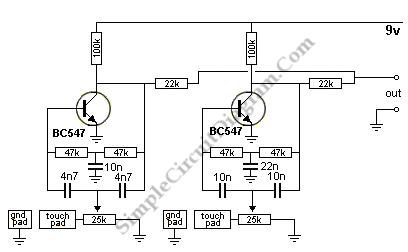
Electronic Drum Synthesizer
The circuit consists of two twin-T oscillators set below the oscillation threshold. To initiate oscillation, a touch on the Touch Pad is required. The schematic diagram illustrates the circuit, where different touch patterns on the pads can create a variety...
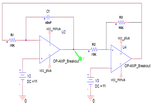
Jammer circuit
The frequency jammer operates by generating interfering RF noise centered around a 2.45 GHz carrier frequency. As the power of this noise increases, the signal-to-noise ratio of the wireless communication channel decreases, leading to a higher bit error rate until...
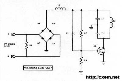
Wireless Telephone Bug
Wireless Telephone Bug. This project enables monitoring of a phone line as soon as the phone is off-hook. A regular FM broadcast band radio can be utilized for this purpose.
The Wireless Telephone Bug is a circuit designed to allow users...
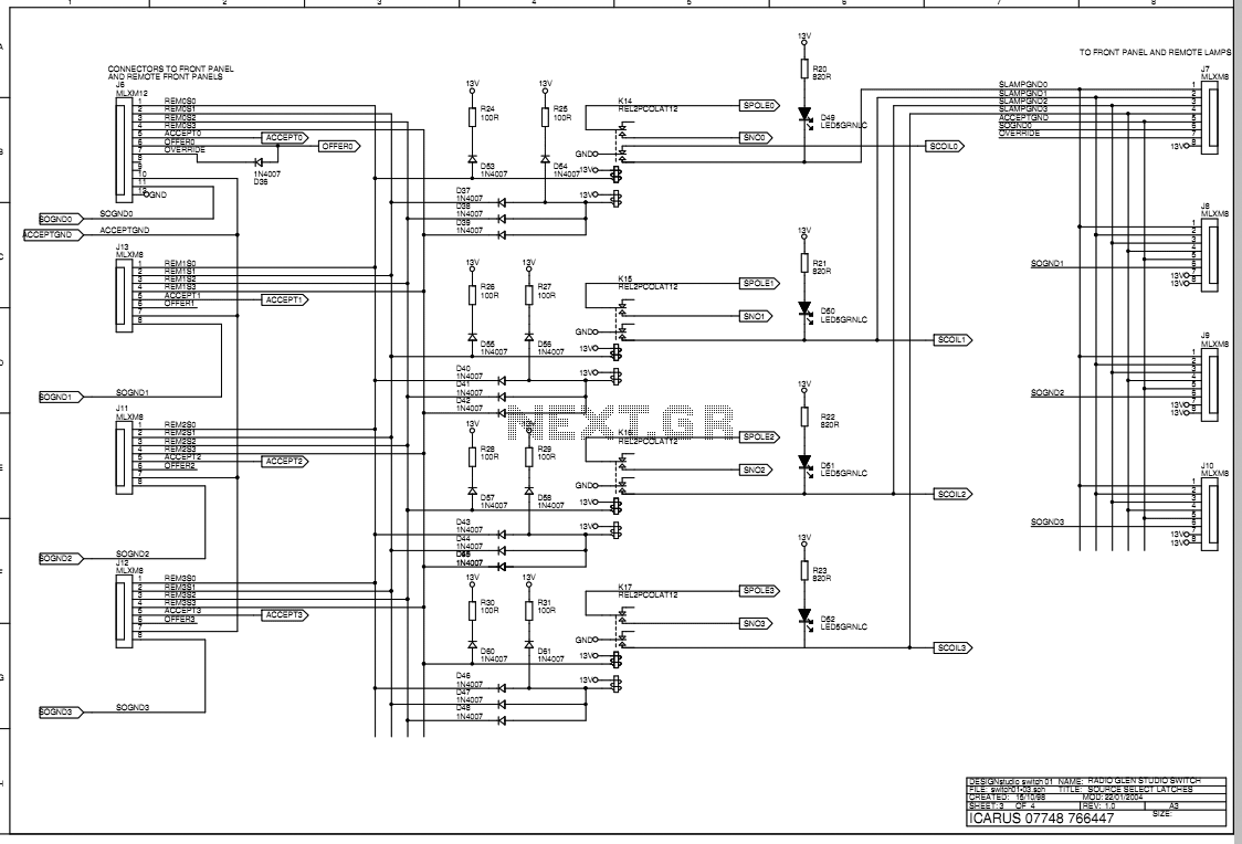
Radio Glen Transmit Selector system
The main box of the Transmit Selector system is designed to be located in the technical rack of a small radio broadcast station. There are four stereo balanced line inputs, either of which can be routed to a stereo balanced...
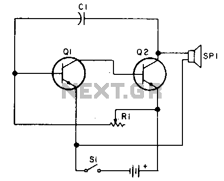
Code practice oscillator II
Oscillator, operates with 2 to 12 volts DC (optimal performance is achieved at 9 to 12 volts for maximum volume and clear keying). Additionally, R1 can be substituted with a 500K potentiometer, allowing the circuit to sweep across the entire...
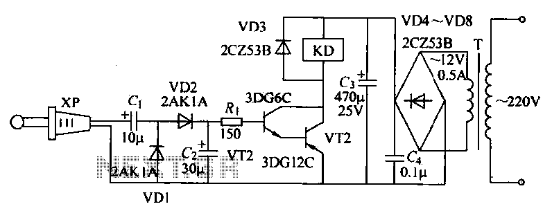
Radio remote control circuit
The receiver circuit depicted in the figure requires the insertion of a plug into the radio headphone jack. When the radio receiver detects a signal from the transmitter, an audio signal is output from the jack. This signal is then...
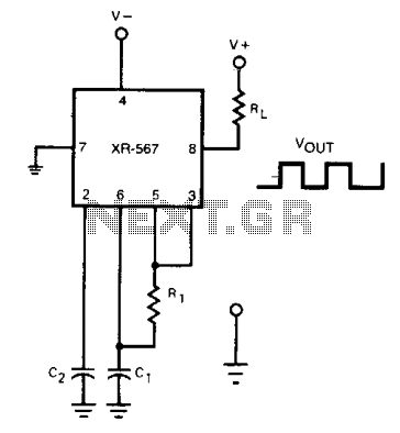
Oscillator with frequency doubled output
The frequency of the current-controlled oscillator can be doubled by feeding a portion of the square-wave output from pin 5 back to the input at pin 3. This configuration allows the quadrature detector to operate as a frequency doubler, resulting...
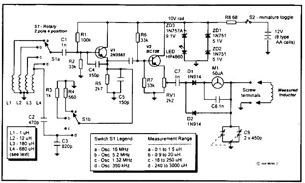
RF Induction Meter
This instrument measures inductances from 0.1 microhenry to 3 millihenries, divided into four ranges set by a switch. It operates from 12 volts and is powered by eight AA type cells attached to the unit. Initially, Drew Diamond's unit in...
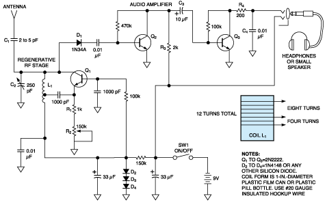
Simple receiver with microvolt sensitivity
The three-transistor circuit costs less than $10 to build, uses commonly available components, and consumes less than 10 mA from a single 9V battery. By winding coil L1 as shown, the circuit can receive signals in the 5 to 15...