


booster radio fm schematic circuit
#FM booster
#RF amplifier
#VHF/UHF transistor
#common-emitter
#tuned RF pre-amplifier
#2SC2570
#distant FM stations
#radio reception
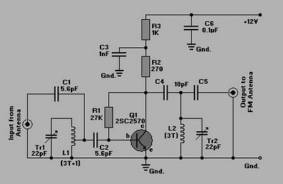
Description: This is a simple circuit of an FM booster designed to enhance the reception of programs from distant FM stations. The amplifier effectively captures signals from far-off FM stations. The configuration is set up as a common-emitter tuned RF pre-amplifier utilizing the VHF/UHF transistor Q1, specifically the 2SC2570 model (only C2570 is marked on the transistor body). It is recommended to assemble the circuit on a high-quality PCB, preferably made of glass-epoxy. Input and output trimmers (VC1/VC2) should be adjusted for optimal gain.
The FM booster circuit operates by amplifying weak radio frequency signals, making it possible to receive distant FM broadcasts with clarity. The core component, the 2SC2570 transistor, is a VHF/UHF transistor known for its high frequency and low noise characteristics, which are essential for effective radio signal amplification.
The common-emitter configuration is chosen for its ability to provide significant voltage gain, which is crucial for boosting weak signals. The circuit typically includes a tuned circuit that helps select the desired frequency while rejecting unwanted signals. This is achieved through the use of inductors and capacitors that form a resonant circuit, ensuring that the amplifier is tuned to the frequency of the FM station being received.
The assembly of the circuit on a glass-epoxy PCB is recommended due to its durability and superior insulating properties, which help maintain signal integrity. The input and output trimmers (VC1 and VC2) are variable capacitors that allow for fine-tuning of the circuit's performance. Adjusting these components optimizes the gain, ensuring the best possible reception of FM signals.
Overall, this FM booster circuit is a valuable tool for enhancing radio reception, particularly in areas where signal strength is weak. Proper assembly and tuning are critical to achieving the desired performance, making this circuit an effective solution for improving FM listening experiences.Here is a simple circuit of an FM booster that can be used to listen to programmes from distant FM stations clearly. This amplifier will pull in all distant FM stations clearly. The circuit is configured as a common-emitter tuned RF pre-amplifier wired around VHF/UHF transistor Q1.
2SC2570. (Only C2570 is annotated on the transistor body. ) Assembl e the circuit on a good-quality PCB (preferably, glass-epoxy). Adjust input/ output trimmers (VC1/VC2) for maximum gain.
The FM booster circuit operates by amplifying weak radio frequency signals, making it possible to receive distant FM broadcasts with clarity. The core component, the 2SC2570 transistor, is a VHF/UHF transistor known for its high frequency and low noise characteristics, which are essential for effective radio signal amplification.
The common-emitter configuration is chosen for its ability to provide significant voltage gain, which is crucial for boosting weak signals. The circuit typically includes a tuned circuit that helps select the desired frequency while rejecting unwanted signals. This is achieved through the use of inductors and capacitors that form a resonant circuit, ensuring that the amplifier is tuned to the frequency of the FM station being received.
The assembly of the circuit on a glass-epoxy PCB is recommended due to its durability and superior insulating properties, which help maintain signal integrity. The input and output trimmers (VC1 and VC2) are variable capacitors that allow for fine-tuning of the circuit's performance. Adjusting these components optimizes the gain, ensuring the best possible reception of FM signals.
Overall, this FM booster circuit is a valuable tool for enhancing radio reception, particularly in areas where signal strength is weak. Proper assembly and tuning are critical to achieving the desired performance, making this circuit an effective solution for improving FM listening experiences.Here is a simple circuit of an FM booster that can be used to listen to programmes from distant FM stations clearly. This amplifier will pull in all distant FM stations clearly. The circuit is configured as a common-emitter tuned RF pre-amplifier wired around VHF/UHF transistor Q1.
2SC2570. (Only C2570 is annotated on the transistor body. ) Assembl e the circuit on a good-quality PCB (preferably, glass-epoxy). Adjust input/ output trimmers (VC1/VC2) for maximum gain.
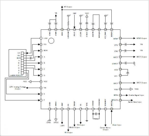
S1L9251X Cd-rom 48x Rf Amp Semiconductor
The SA1021 integrated radio receiver circuit is designed for portable radios, supporting both stereo and mono output while emphasizing minimal peripheral components for compact size and low cost. It is fully compatible with applications utilizing the low-voltage micro tuning system...
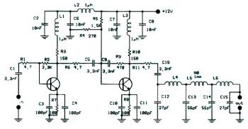
1w fm booster based 2n4427
This circuit diagram illustrates a linear FM booster and RF amplifier utilizing the Philips 2N4427 transistor. The RF amplifier is designed to enhance the performance of small FM transmitters and bugs, employing two Philips 2N4427 transistors, delivering approximately 1 Watt...
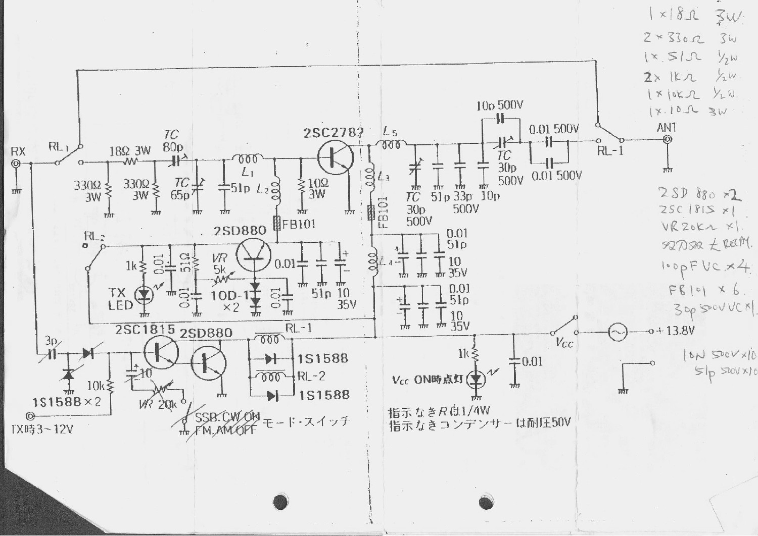
100W Transmitter RF Power Amplifier 2SC2782
This is a 6-meter band transmitter RF power amplifier (50 MHz) with a 100W output. It is compatible with the FT-736R and is driven by a 10W signal for 6m SSB DX. The construction information is sourced from Japan CQ...
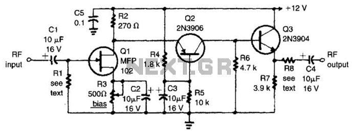
Broadcast Band Rf Amplifier Circuit
The circuit features a frequency response that spans from 100 Hz to 3 MHz, with a gain of approximately 30 dB. Field-effect transistor Q1 is arranged in a common-source self-biased configuration, and an optional resistor R1 is available to adjust...
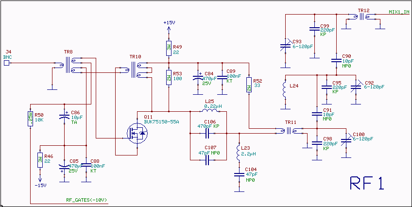
10.7 MHz RF Amplifier And Filter
The following circuit illustrates a 10.7 MHz RF amplifier and filter circuit diagram. Features include significant capacitances of a power MOSFET.
The 10.7 MHz RF amplifier and filter circuit is designed to amplify radio frequency signals while simultaneously filtering out unwanted...
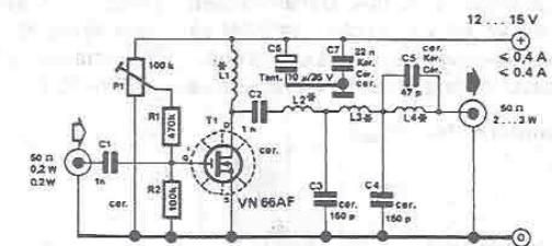
RF amplifier circuit diagram
By using this RF amplifier, small power transmitters of 200 mW can be upgraded to reasonable power transmitters, ranging between 2 and 3 W. The circuit is straightforward. The output filter network suppresses noise by at least 55 dB. The...
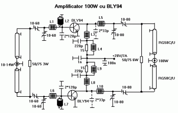
100W RF Amplifier Circuit With BLY94 Transistor
This is a component of a 100W RF amplifier. This circuit is constructed using the RF power transistor BLY94. Components include the BLY94 transistor, inductor, and others.
The 100W RF amplifier circuit utilizing the BLY94 transistor is designed to amplify radio...
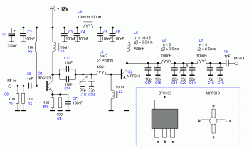
15w rf amplifier circuit
An RF power amplifier is a type of electronic amplifier used to convert a low-power radio-frequency signal into a larger signal of significant power, typically for driving the antenna of a transmitter. It is optimized for high efficiency, high output...
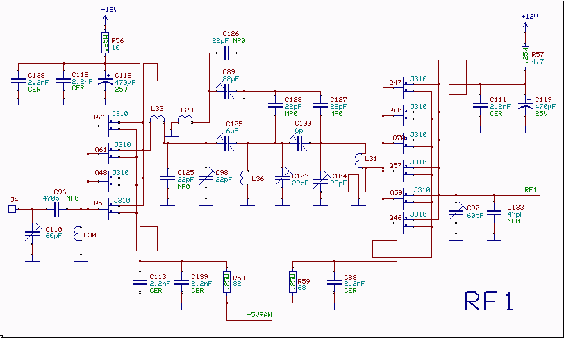
RF amplifier and filter for 144 MHz
The RF amplifiers utilize noiseless feedback through the drain-gate capacitance, incorporating an inductor in the source lead to achieve the necessary 90-degree phase shift between the gate voltage and channel current. The first RF amplifier provides approximately 4 dB of...