


Bruces TPU Theory and Experiments
Warning: Undefined array key "extension" in /var/www/html/nextgr/view-circuit.php on line 445
Deprecated: strtolower(): Passing null to parameter #1 ($string) of type string is deprecated in /var/www/html/nextgr/view-circuit.php on line 445

Description: SM indicates that the tube can produce certain frequencies and discusses the use of TV tubes to achieve improved sound quality at higher frequencies. The effectiveness of this approach can only be determined through experimentation with the specified frequency ranges. The next step involves tuning the amplifier to the TPU (Tesla Power Unit). After tuning the TPU according to previously outlined steps, it is essential to measure its impedance. The amplifier selected must match this impedance to avoid distortion, which can hinder performance and prevent the desired catalyst effect. A tube circuit is being utilized, and its design was paused to analyze new information provided by Turbo. Impedance, defined as a derived unit of resistance, capacitance, and inductance, is measured in Ohms but can be complex and sometimes misleading. For instance, a speaker's impedance may be rated at 8 Ohms but can vary with frequency. The tube circuit aims to match the amplifier impedance to the tuned TPU and a specific frequency of 35.705 kHz. The signal from the amplifier to the speaker travels at the speed of light, highlighting the importance of speed as a form of energy. Amplification refers to increasing signal strength, with voltage amplification characterized by the gain ratio of output to input voltage. For example, a 10mV input could be amplified to 1 Volt, indicating a voltage gain of 100. Current amplification follows a similar principle, where a 10mA input could be increased to 1A, also representing a gain of 100. Feedback is crucial for frequency control in solid-state devices, but it can pose challenges for generators. It involves routing a portion of the output signal back to the input, which is essential for achieving high performance in many amplifier types.
The circuit design focuses on achieving optimal performance through precise impedance matching between the TPU and the amplifier. This is critical to ensure that the system operates without distortion, which could compromise the overall sound quality and effectiveness of the circuit. The process begins with tuning the TPU, which must be done carefully according to established guidelines. Once tuned, measuring the TPU's impedance provides the necessary data to select an appropriate amplifier. The amplifier must have an impedance rating that aligns with the TPU to maintain signal integrity.
In the context of tube amplifiers, the design should emphasize the characteristics of the tube used, as it can significantly influence the sound quality and frequency response. The use of TV tubes, known for their ability to handle higher frequencies, can enhance the overall audio experience. The circuit should include provisions for adjusting various parameters, including gain and feedback levels, to tailor the performance to specific audio applications.
The amplification process must be understood in terms of both voltage and current. The voltage gain is a critical measure, as it determines how much the input signal is increased. The design should incorporate feedback mechanisms to maintain stability and control over the amplification process, while also considering the potential drawbacks of excessive feedback, which can introduce noise and reduce clarity in audio applications.
Overall, the schematic should reflect a comprehensive understanding of impedance, amplification, and feedback principles, ensuring that the circuit operates efficiently and effectively while delivering high-quality audio performance. The integration of these elements will result in a robust design capable of meeting the demands of modern audio applications.SM is merely pointing out that the tube is capable of producing those frequencies. he talks about using TV tubes to get a better sound at higher frequencies. anyways it doesnt matter what we think he is saying. just experiment it and see if u get anything from those pointed ranges. it is the only way to be certain. Okay, the next tuning is that of the amplifier to the TPU. Once your TPU is tuned according to the steps mentioned a few posts previous, you need to measure the impedance. This then is the impedance that your choice of amplifier must also be. IF THE amplifier impedance does not match that of the TPU there can be DISTORTION. And we all know by now what that means. NO CATALYST! Now as you know, I will be using a tube circuit. It was in the middle of being designed when Turbo released his wonderful compilation of additional material. I put a halt to the circuit until I could analyze all of the new material. "A derived unit of resistance, capacitance and inductance in combination is called impedance, although it is not a requirement that all three be included.
Impedance is also measured in Ohms, but is a very complex figure, and often fails completely to give you any useful information. The impedance of a speaker is a case in point. Although the brochure may state that a speaker has an impedance of 8 Ohms, in reality it will vary depending on frequency" I am glad that "I am not in a hurry"!
LOL For now my Tube guy will match the impedance of the amp to my "tuned" tpu AND to the correct frequency of 35. 705 KHz For those who do not yet understand the collectors can restudy SM`s clue of the engineering of the plane that broke the sound barrier, or reread my thread on the matter.
I also found out that the "signal" from the Amp to the speaker travels at the speed of light. Some of you will understand the significance of that! SPEED is energy! The term "amplify" basically means to make stronger. The strength of a signal (in terms of voltage) is referred to as amplitude, but there is no equivalent for current (curritude, nah, sounds silly). This in itself is confusing, because although "amplitude" refers to voltage, it contains the word "amp", as in ampere.
Maybe we should introduce "voltitude" - No Just live with it. In the case of a voltage amplifier, a small input voltage will be increased, so that for example a 10mV (0. 01V) input signal might be amplified so that the output is 1 Volt. This represents a "gain" of 100 - the output voltage is 100 times as great as the input voltage. This is called the voltage gain of the amplifier. In the case of a current amplifier, an input current of 10mA (0. 01A) might be amplified to give an output of 1A. Again, this is a gain of 100, and is the current gain of the amplifier. "# 3. As you know, Large amounts of FEEDBACK is essential to frequency and control when using SS devices for everything in the electronics world, HOWEVER, it is the enemy of generators!" Feedback is a term that creates more and bloodier battles between audio enthusiasts than almost any other.
Without it, we would not have the levels of performance we enjoy today, and many amplifier types would be unlistenable without it. Feedback in its broadest sense means that a certain amount of the output signal is "fed back" into the input.
An amplifier - or an element of an amplifying device - is presented with the input signal, and compares it to a "small scale replica
The circuit design focuses on achieving optimal performance through precise impedance matching between the TPU and the amplifier. This is critical to ensure that the system operates without distortion, which could compromise the overall sound quality and effectiveness of the circuit. The process begins with tuning the TPU, which must be done carefully according to established guidelines. Once tuned, measuring the TPU's impedance provides the necessary data to select an appropriate amplifier. The amplifier must have an impedance rating that aligns with the TPU to maintain signal integrity.
In the context of tube amplifiers, the design should emphasize the characteristics of the tube used, as it can significantly influence the sound quality and frequency response. The use of TV tubes, known for their ability to handle higher frequencies, can enhance the overall audio experience. The circuit should include provisions for adjusting various parameters, including gain and feedback levels, to tailor the performance to specific audio applications.
The amplification process must be understood in terms of both voltage and current. The voltage gain is a critical measure, as it determines how much the input signal is increased. The design should incorporate feedback mechanisms to maintain stability and control over the amplification process, while also considering the potential drawbacks of excessive feedback, which can introduce noise and reduce clarity in audio applications.
Overall, the schematic should reflect a comprehensive understanding of impedance, amplification, and feedback principles, ensuring that the circuit operates efficiently and effectively while delivering high-quality audio performance. The integration of these elements will result in a robust design capable of meeting the demands of modern audio applications.SM is merely pointing out that the tube is capable of producing those frequencies. he talks about using TV tubes to get a better sound at higher frequencies. anyways it doesnt matter what we think he is saying. just experiment it and see if u get anything from those pointed ranges. it is the only way to be certain. Okay, the next tuning is that of the amplifier to the TPU. Once your TPU is tuned according to the steps mentioned a few posts previous, you need to measure the impedance. This then is the impedance that your choice of amplifier must also be. IF THE amplifier impedance does not match that of the TPU there can be DISTORTION. And we all know by now what that means. NO CATALYST! Now as you know, I will be using a tube circuit. It was in the middle of being designed when Turbo released his wonderful compilation of additional material. I put a halt to the circuit until I could analyze all of the new material. "A derived unit of resistance, capacitance and inductance in combination is called impedance, although it is not a requirement that all three be included.
Impedance is also measured in Ohms, but is a very complex figure, and often fails completely to give you any useful information. The impedance of a speaker is a case in point. Although the brochure may state that a speaker has an impedance of 8 Ohms, in reality it will vary depending on frequency" I am glad that "I am not in a hurry"!
LOL For now my Tube guy will match the impedance of the amp to my "tuned" tpu AND to the correct frequency of 35. 705 KHz For those who do not yet understand the collectors can restudy SM`s clue of the engineering of the plane that broke the sound barrier, or reread my thread on the matter.
I also found out that the "signal" from the Amp to the speaker travels at the speed of light. Some of you will understand the significance of that! SPEED is energy! The term "amplify" basically means to make stronger. The strength of a signal (in terms of voltage) is referred to as amplitude, but there is no equivalent for current (curritude, nah, sounds silly). This in itself is confusing, because although "amplitude" refers to voltage, it contains the word "amp", as in ampere.
Maybe we should introduce "voltitude" - No Just live with it. In the case of a voltage amplifier, a small input voltage will be increased, so that for example a 10mV (0. 01V) input signal might be amplified so that the output is 1 Volt. This represents a "gain" of 100 - the output voltage is 100 times as great as the input voltage. This is called the voltage gain of the amplifier. In the case of a current amplifier, an input current of 10mA (0. 01A) might be amplified to give an output of 1A. Again, this is a gain of 100, and is the current gain of the amplifier. "# 3. As you know, Large amounts of FEEDBACK is essential to frequency and control when using SS devices for everything in the electronics world, HOWEVER, it is the enemy of generators!" Feedback is a term that creates more and bloodier battles between audio enthusiasts than almost any other.
Without it, we would not have the levels of performance we enjoy today, and many amplifier types would be unlistenable without it. Feedback in its broadest sense means that a certain amount of the output signal is "fed back" into the input.
An amplifier - or an element of an amplifying device - is presented with the input signal, and compares it to a "small scale replica
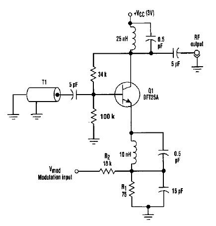
Varactorless high frequency modulator circuit design electronic project
This varactorless high-frequency modulator electronic project must be powered by a simple DC 3-volt power source, such as a 3-volt battery. Traditionally, high-frequency oscillators are frequency-modulated using a varactor. However, varactors typically require a significant voltage change to achieve an...
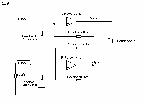
Amplifier Bridging
The primary advantage of this method of bridging is that no additional components are needed, which means that it is cheap, and there is no signal degradation from additional opamps in the circuit path. The results are at least as...
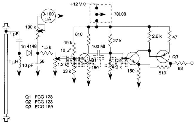
General-Purpose Output Amplifier Circuit
This general-purpose amplifier has a bandwidth of approximately 20 MHz and it uses an LM733/NE592 video amplifier integrated circuit. This circuit can be utilized as a line driver or as a LAN line driver.
The circuit employs the LM733/NE592 video amplifier...
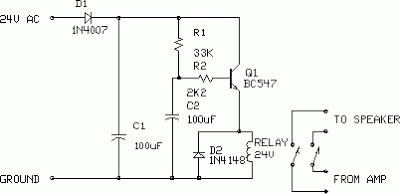
Amplifier Output Delay with Relay Schematic Diagram
This is a minimal circuit designed for individual audio amplifier projects to control the presenter output relay. The purpose of this circuit is to manage the relay that activates the speaker output within the audio amplifier. The circuit introduces a...
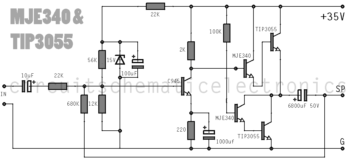
simple-amplifier-with-c945mje340-and.html
This simple amplifier delivers good sound quality with a power output of approximately 10 to 14 Watts and operates on a supply voltage of about 34 to 36 Volts DC. It requires a preamplifier due to its limited advanced features....
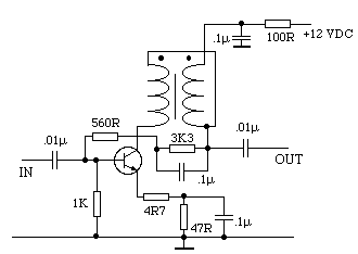
RECEIVER BUILDING BLOCKS
This amplifier has about 20dB of gain, bandwidth of 100MHz and noise figure of about 7dB. The output transformer is 8 turns bifilar wound on a ferrite core. Use a medium power UHF transistor 2N5109, 2N3866, 2N4427 or similar. The...
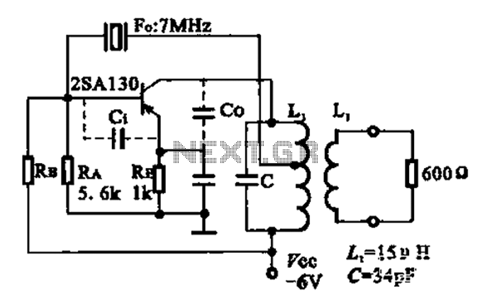
7MHz high frequency carrier oscillator
The 2SA130 transistor is used in an oscillator circuit with an oscillation frequency of 7 MHz. The power supply voltage is 6V, and the load is a frequency-selective resonant circuit with a quality factor of 600.
The circuit utilizes the 2SA130...
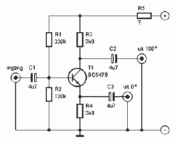
Amplifiers connecting Bridge
This is a circuit that ensures that you can connect two amplifiers together so you get more power. When called in bridge linking two amplifiers plus you can link the outputs of the amplifiers to the speaker. One of the...
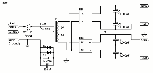
Power Supply For Amplifiers
For the 60W amplifier, a nominal (full load) supply of +/- 35V is required, so a 25-0-25 secondary is ideal - however, see Updates, below. The circuit for the supply is shown below, and uses separate rectifiers, capacitors and fuses...