


Cb modulation monitor
#CB radio
#modulation
#transceiver
#coaxial
#transmission line
#calibration
#RF monitoring
#communication
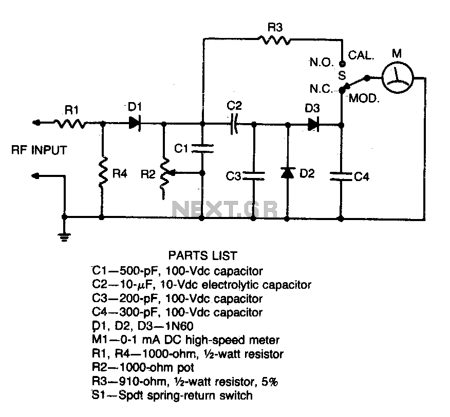
Description: Connect this circuit to a transceiver using a coaxial T connector in the transmission line. Activate the transmitter (unmodulated), set switch 31 to CAL, and adjust resistor R2 for a full-scale reading. Return switch SI to the MOD position. The meter will display percentage modulation with an accuracy of 10%.
This circuit is designed for measuring the percentage of modulation in a transmission line by interfacing with a transceiver. The use of a coaxial T connector allows for seamless integration into the transmission line without significant signal loss.
Upon connecting the circuit, the transmitter should be keyed in an unmodulated state, ensuring that the signal being analyzed is a constant carrier wave. Setting switch 31 to the CAL position is essential for calibrating the circuit, allowing it to provide accurate readings. The adjustment of resistor R2 is critical; it must be fine-tuned to achieve a full-scale reading on the meter, which indicates that the circuit is properly calibrated to the specific characteristics of the transceiver and the modulation being measured.
Once calibrated, switch SI should be returned to the MOD position. In this configuration, the circuit will measure the modulation depth of the signal, providing a readout on the meter that reflects the percentage of modulation. The meter is designed to deliver readings with an accuracy of 10%, which is sufficient for many practical applications in radio transmission and communication systems. This level of accuracy ensures that users can monitor modulation levels effectively, facilitating optimal performance and compliance with transmission standards.
This circuit is particularly useful in settings where modulation levels must be monitored and adjusted to meet specific criteria, such as in broadcasting, amateur radio, and communications testing environments. Proper operation and calibration of this circuit contribute to enhanced signal quality and reliability in radio frequency applications.Connect this circuit to a transceiver with a coaxial T connector in the transmission line. Key the transmitter (unmodulated), set 31 to CAL, and adjust R2 for a full scale reading. Return SI to MOD position The meter will read % modulation with 10% accuracy.
This circuit is designed for measuring the percentage of modulation in a transmission line by interfacing with a transceiver. The use of a coaxial T connector allows for seamless integration into the transmission line without significant signal loss.
Upon connecting the circuit, the transmitter should be keyed in an unmodulated state, ensuring that the signal being analyzed is a constant carrier wave. Setting switch 31 to the CAL position is essential for calibrating the circuit, allowing it to provide accurate readings. The adjustment of resistor R2 is critical; it must be fine-tuned to achieve a full-scale reading on the meter, which indicates that the circuit is properly calibrated to the specific characteristics of the transceiver and the modulation being measured.
Once calibrated, switch SI should be returned to the MOD position. In this configuration, the circuit will measure the modulation depth of the signal, providing a readout on the meter that reflects the percentage of modulation. The meter is designed to deliver readings with an accuracy of 10%, which is sufficient for many practical applications in radio transmission and communication systems. This level of accuracy ensures that users can monitor modulation levels effectively, facilitating optimal performance and compliance with transmission standards.
This circuit is particularly useful in settings where modulation levels must be monitored and adjusted to meet specific criteria, such as in broadcasting, amateur radio, and communications testing environments. Proper operation and calibration of this circuit contribute to enhanced signal quality and reliability in radio frequency applications.Connect this circuit to a transceiver with a coaxial T connector in the transmission line. Key the transmitter (unmodulated), set 31 to CAL, and adjust R2 for a full scale reading. Return SI to MOD position The meter will read % modulation with 10% accuracy.

N6EX Exciter Mods
This document outlines the necessary hardware modifications to adapt a Kenwood TK-931 transceiver for use as a 2-watt exciter for 927 MHz repeater service. The programming of the radio for the desired operating frequency is not included here, as it...
F6DQM Software Interfacing you computer
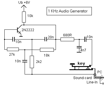
Additional examples for connecting transceivers to a computer for SIMPLEX software operations are detailed in the pc_tx.bmp file included in the simplex.zip file.
The provided information indicates that the pc_tx.bmp file contains visual representations or diagrams that illustrate various methods for...
Modulation-monitor
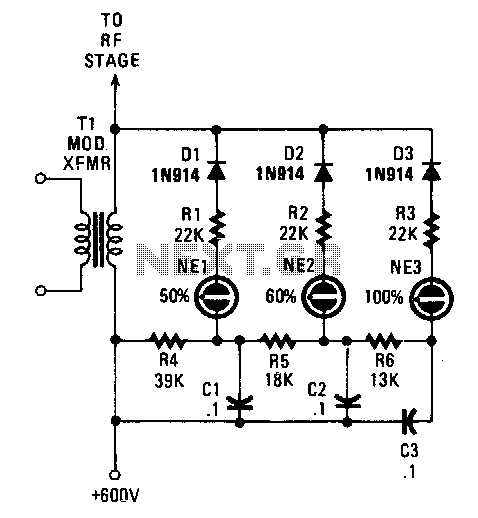
Switching diodes are utilized to activate the neon lamps when negative-peak modulation reaches 50%, 60%, and 100%. To operate the circuit effectively, it is important to monitor the lamps. The 50% lamp should ideally be firing continuously, the 60% lamp...
modulation
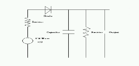
A reason to modulate a message signal is to match the communication channel's frequency. This is necessary because the information to be sent over the channel is often at a relatively low frequency. For instance, the frequency range of music...
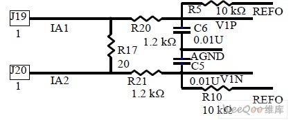
Design and realizing of the electric transmission line monitoring system
Observing and addressing the phase adjustment issues in electric transmission lines manually poses significant challenges, particularly in recording and normalizing three major problems. This design encompasses both software and hardware components, developed over an extended period. It is intended to...
ic718
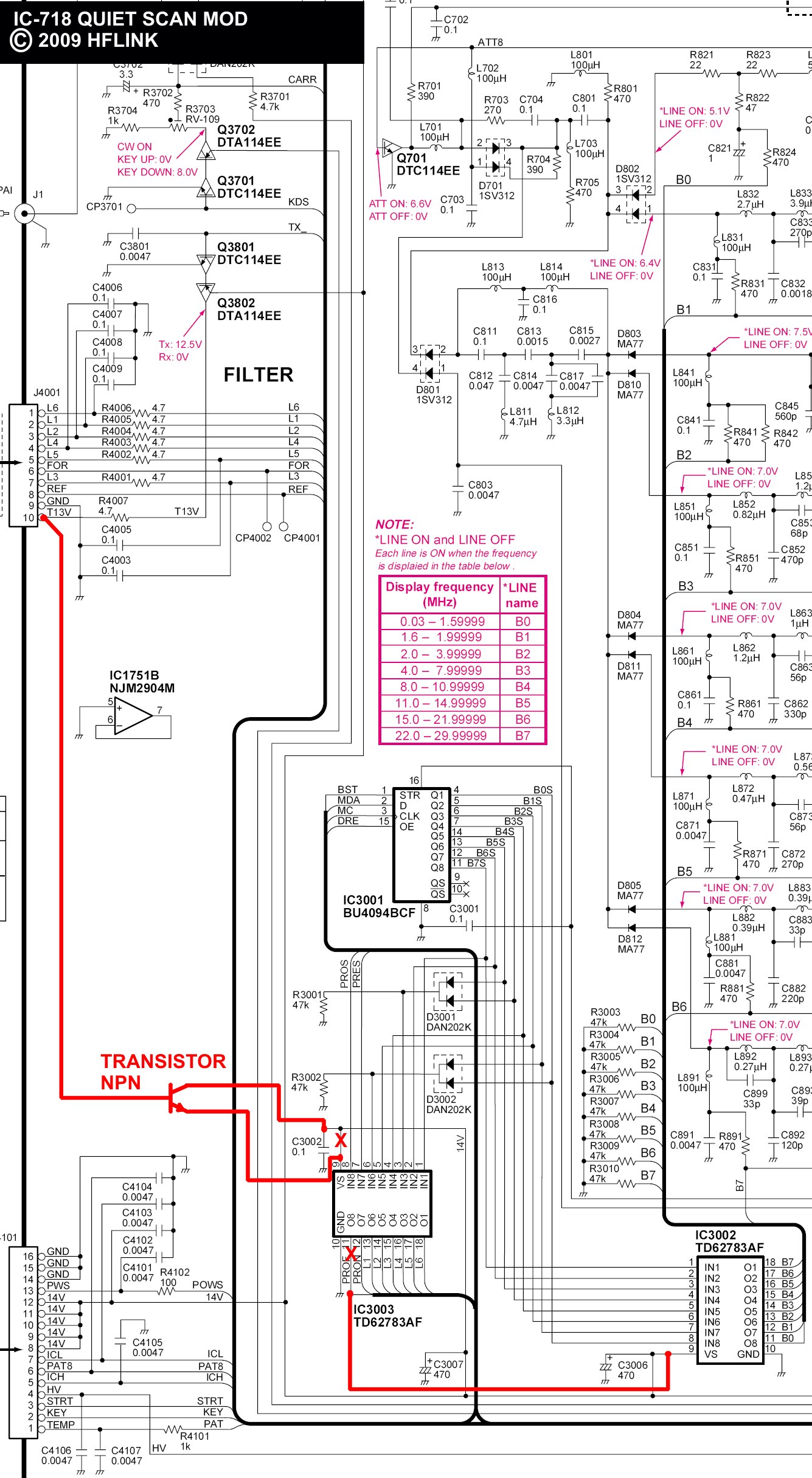
Modification of the Icom IC-718 Transceiver for Automatic Link Establishment (ALE), to deactivate the transmit bandpass relays during receive and scanning.
The modification of the Icom IC-718 Transceiver for ALE involves a specific alteration to the circuitry that controls the operation...
HAM ATS3a digital
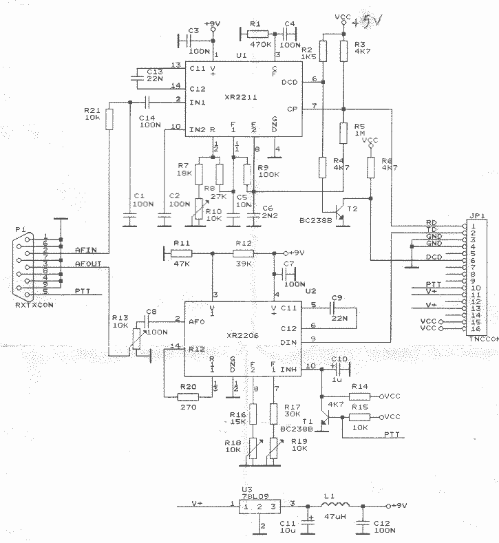
The stock ATS-3A transceiver has been modified to transmit BPSK31 signals, specifically "cq ok1iak." The firmware was altered to enable serial line control through the DASH paddle pin while in straight key mode, which disables the paddle in remote control...
Yves OESCH HB9DTX Transceivers modifications
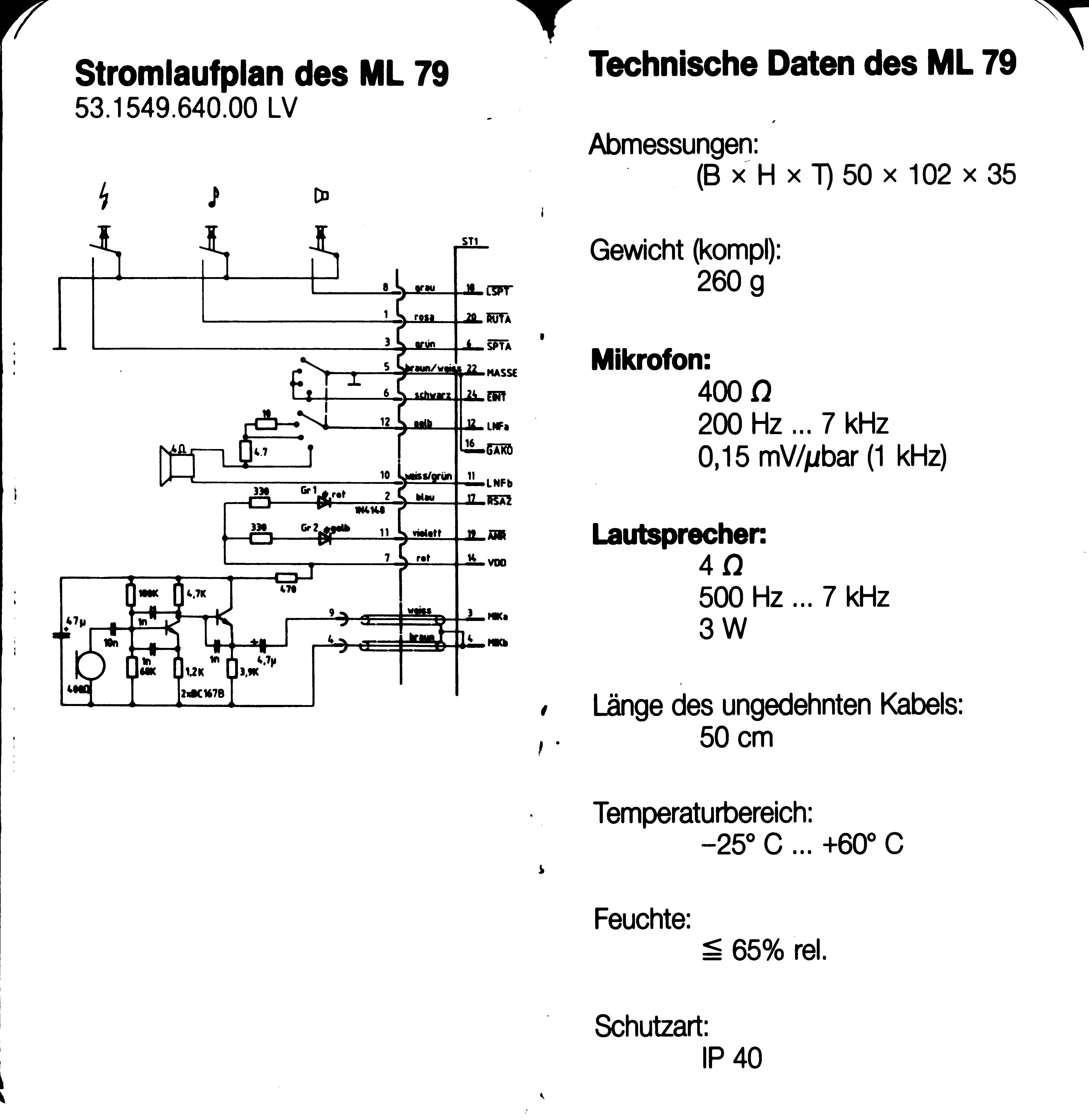
The original firmware is functional on amateur radio bands; however, it lacks user-friendliness. Wulf-Gerd, DL1FAC, has developed a new firmware that is significantly more suitable for amateur radio users. This firmware is open source, allowing for flexible frequency adjustments, power...
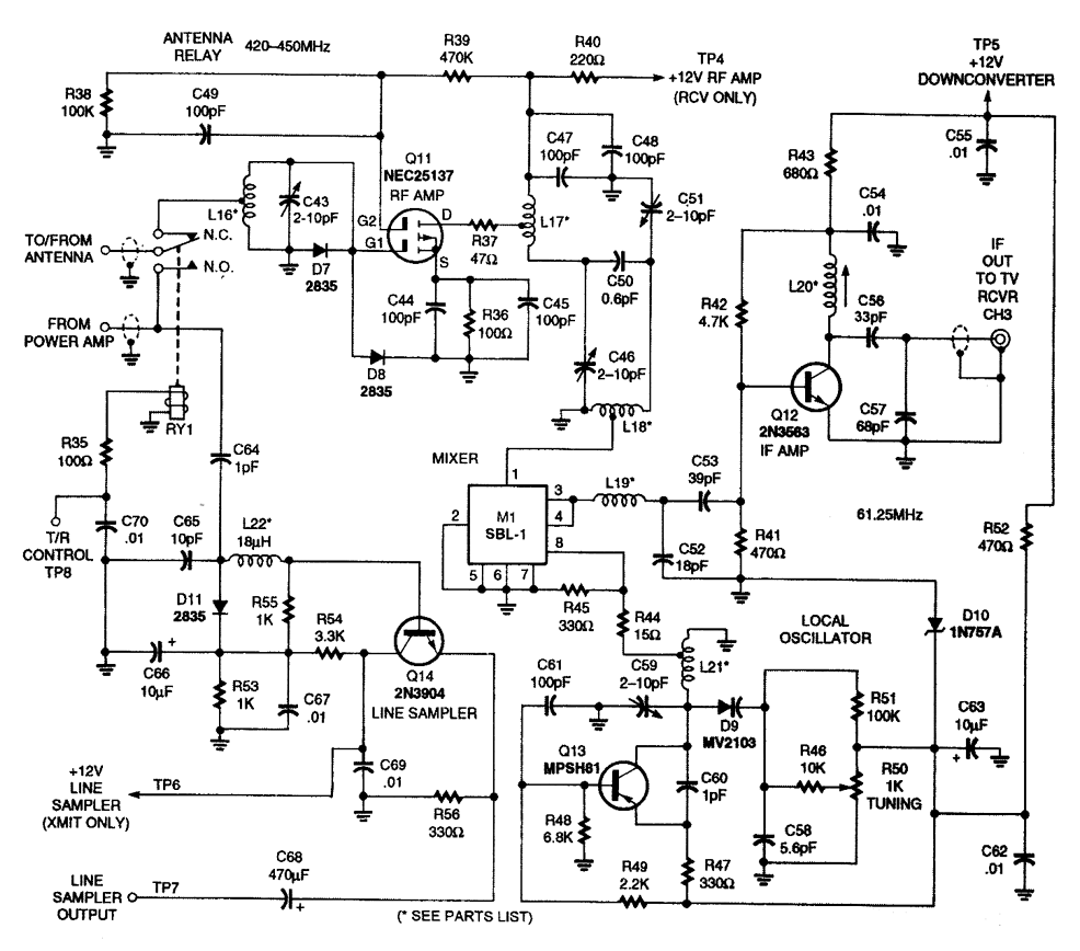
5 W ATV TRANSCEIVER
The transmitter schematic, which is a component of the transceiver, can be found in the entry titled S-W ATV Transmitter for 440 MHz, Figure 5-1. The downconverter section is illustrated here. This transmitter includes both video and audio sections, producing...