


Circuit diagram 500mW FM PLL transmitter 88-108MHz using LMX3206 and PIC16F870
#FM transmitter
#PLL
#LMX3206
#PIC16F870
#Colpitts oscillator
#frequency modulation
#HF transistor
#LC tank
#88-108MHz
#RF circuit
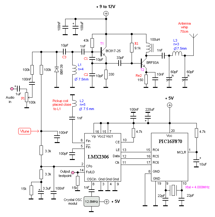
Description: This oscillator is known as the Colpitts oscillator and is voltage-controlled to facilitate frequency modulation (FM) and phase-locked loop (PLL) control. The transistor T1 should be a high-frequency (HF) transistor for optimal performance; however, in this instance, a common and inexpensive BC817 transistor is utilized. The LC tank circuit is essential for proper oscillation. It should be noted that the output signal has an asymmetrical waveform, with positive pulses lasting only a few microseconds, making it challenging to observe on an oscilloscope. This issue is addressed by connecting the oscillator output to a 74HC4020 (14-stage Binary Counter) at input pin 10. A symmetrical square wave, with a frequency that is half of the original, can be obtained from Q0 (pin 9), while Q1 (pin 7) provides a frequency divided by 4; refer to the datasheet for additional details. A potentiometer, P1, is incorporated to adjust the modulation depth, allowing for wide or narrow FM. The value of P1 may require experimentation, as it can significantly affect modulation levels; a potentiometer in the range of 500k to 1M ohms may be necessary for optimal performance. Resistors R1 and Re2 are used to regulate the DC current flow. In this case, a resistance value of 9.1k ohms has been found to yield satisfactory output power, approximately equal to 150. To increase the output power, it may be necessary to reduce the value of Re2, or an additional 150-ohm resistor can be added in parallel.
The Colpitts oscillator is a type of LC oscillator that utilizes a combination of inductance (L) and capacitance (C) to generate oscillations. The unique configuration of the Colpitts oscillator allows for the generation of stable frequencies, making it suitable for applications in RF transmission and signal processing. The choice of the BC817 transistor, while not an HF transistor, serves as a practical solution for low-cost applications, but may limit the frequency range and performance compared to higher-grade transistors.
The LC tank circuit consists of a capacitor and inductor, which resonate at a specific frequency determined by their values. The frequency of oscillation can be calculated using the formula:
\[ f = \frac{1}{2\pi\sqrt{LC}} \]
In this configuration, the modulation capabilities are enhanced by the integration of the 74HC4020 binary counter. This device enables frequency division, allowing the output signal to be manipulated for various applications. The use of a potentiometer for modulation depth provides flexibility in tuning the oscillator for different signal requirements, which is a critical aspect in communication systems where signal clarity and bandwidth are essential.
The resistors R1 and Re2 play a pivotal role in controlling the biasing and stability of the transistor, ensuring that the oscillator operates within the desired parameters. The suggested values for these resistors are based on empirical testing, and adjustments may be necessary depending on the specific circuit conditions and desired output characteristics.
Overall, the Colpitts oscillator circuit described offers a versatile platform for generating frequency-modulated signals, with the potential for further enhancements and modifications based on user requirements and application scenarios.This oscillator is called the Colpitts oscillator and voltage controlled to achieve the FM (frequency modulation) and PLL control. T1 must be HF transistors to work well, but in this case I use a cheap and common BC817 transistor. LC tank oscillator needs to oscillate properly. (I must warn you that the signal is not symmetrical in form. Pulsa pos itive only a few microseconds, so you will be hard to see on the oscilloscope. ) I solved by connecting it to 74HC4020 (14-stage Binary Counter) to input pin 10 Hours. In Q0 (pin 9) you will have a symmetrical square wave with a frequency half since the circuit is a table. In Q1 pin 7 will be divided by 4, see data sheet for more information. A potentiometer P1 was added to adjust the depth of modulation (FM Wide or Narrow FM). You may have to play a bit with a value of P1 because it tends to modulate the lot. You may need to add the 500k 1M potentiometer only. You test and find out for himself. Resistor R1 and resistor Re2 regulate the flow of DC. In this case I find that 9. 1k will give a good output power and thus equal to 150. If you want to increase the power should be lower Re2. You can add another 150 ohm resistor in parallel.
The Colpitts oscillator is a type of LC oscillator that utilizes a combination of inductance (L) and capacitance (C) to generate oscillations. The unique configuration of the Colpitts oscillator allows for the generation of stable frequencies, making it suitable for applications in RF transmission and signal processing. The choice of the BC817 transistor, while not an HF transistor, serves as a practical solution for low-cost applications, but may limit the frequency range and performance compared to higher-grade transistors.
The LC tank circuit consists of a capacitor and inductor, which resonate at a specific frequency determined by their values. The frequency of oscillation can be calculated using the formula:
\[ f = \frac{1}{2\pi\sqrt{LC}} \]
In this configuration, the modulation capabilities are enhanced by the integration of the 74HC4020 binary counter. This device enables frequency division, allowing the output signal to be manipulated for various applications. The use of a potentiometer for modulation depth provides flexibility in tuning the oscillator for different signal requirements, which is a critical aspect in communication systems where signal clarity and bandwidth are essential.
The resistors R1 and Re2 play a pivotal role in controlling the biasing and stability of the transistor, ensuring that the oscillator operates within the desired parameters. The suggested values for these resistors are based on empirical testing, and adjustments may be necessary depending on the specific circuit conditions and desired output characteristics.
Overall, the Colpitts oscillator circuit described offers a versatile platform for generating frequency-modulated signals, with the potential for further enhancements and modifications based on user requirements and application scenarios.This oscillator is called the Colpitts oscillator and voltage controlled to achieve the FM (frequency modulation) and PLL control. T1 must be HF transistors to work well, but in this case I use a cheap and common BC817 transistor. LC tank oscillator needs to oscillate properly. (I must warn you that the signal is not symmetrical in form. Pulsa pos itive only a few microseconds, so you will be hard to see on the oscilloscope. ) I solved by connecting it to 74HC4020 (14-stage Binary Counter) to input pin 10 Hours. In Q0 (pin 9) you will have a symmetrical square wave with a frequency half since the circuit is a table. In Q1 pin 7 will be divided by 4, see data sheet for more information. A potentiometer P1 was added to adjust the depth of modulation (FM Wide or Narrow FM). You may have to play a bit with a value of P1 because it tends to modulate the lot. You may need to add the 500k 1M potentiometer only. You test and find out for himself. Resistor R1 and resistor Re2 regulate the flow of DC. In this case I find that 9. 1k will give a good output power and thus equal to 150. If you want to increase the power should be lower Re2. You can add another 150 ohm resistor in parallel.
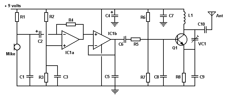
FM Transmitter Circuit
An FM transmitter circuit that utilizes a low power configuration, employing an operational amplifier as an audio preamplifier and a single transistor to function as the RF amplifier.
This FM transmitter circuit is designed for low power applications, making it...
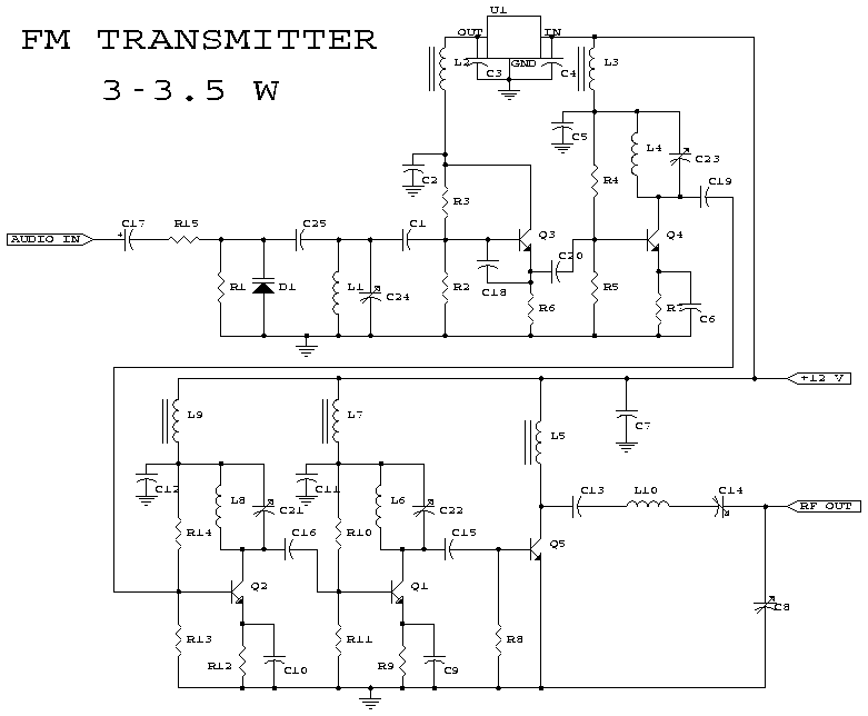
3w fm transmitter
This schematic represents an FM transmitter capable of delivering an output power of 3 to 3.5 W, operating within the frequency range of 90 to 110 MHz. While the stability of the circuit is acceptable, a Phase-Locked Loop (PLL) can...
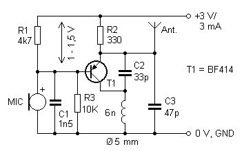
Micro Transmitter Bug
The presented FM transmitter circuit is constructed using BF414, BF324, or BF606 transistors. It features a 30 cm antenna that provides a range of approximately 30 meters indoors and even greater range outdoors. The power supply consists of two AAA...
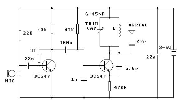
300m FM Transmitter
This FM transmitter circuit is simple and provides acceptable transmission. The signal transmitted from this FM transmitter circuit can be received at...
This FM transmitter circuit utilizes a few basic components to generate frequency-modulated signals suitable for short-range transmission. The primary...

Single Transistor FM Transmitter Design
In telecommunications, Frequency Modulation (FM) transmits information over a carrier wave by varying its frequency. FM is widely utilized at VHF radio frequencies for high-fidelity broadcasts of music and speech. The global broadcast band is situated within the VHF segment...
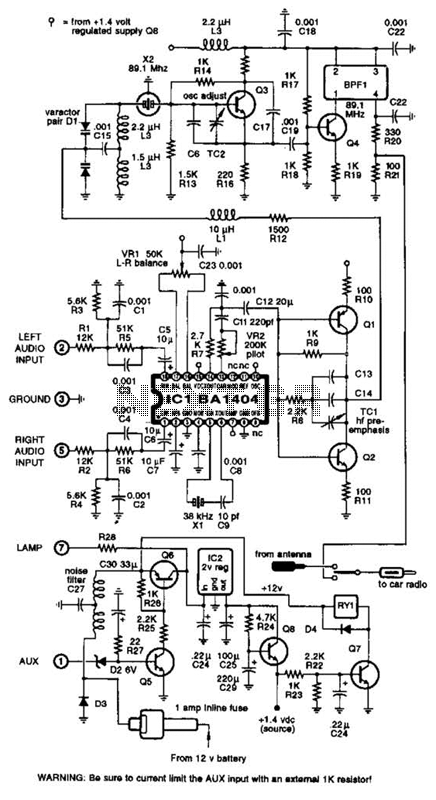
Fm Stereo Transmitter Circuit
A BA1404 integrated circuit (IC) is utilized to generate a complete FM multiplex (MPX) signal. The chip incorporates all necessary circuitry. Components CI, R3, R4, and C4 are responsible for providing pre-emphasis. The transmitter operates on a single AA cell....
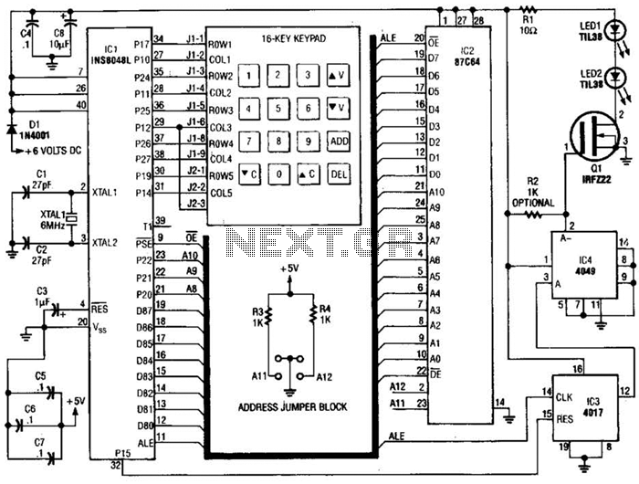
Remote-Control Transmitter Circuit
This transmitter emits an FM signal within the 88 to 108 MHz frequency range, featuring a tone of 19 kHz. This tone can activate the FM MPX pilot carrier indicator, allowing interfacing with external devices. L4 is designed for use...
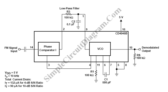
PLL FM Demodulator
A Phase Locked Loop (PLL) can be utilized to create a Frequency Modulation (FM) demodulator. The PLL circuit tracks the input frequency by adjusting the voltage input of a Voltage-Controlled Oscillator (VCO).
The Phase Locked Loop (PLL) is a critical component...
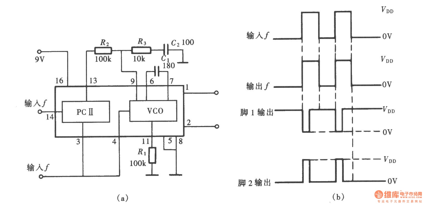
Frequency signal tracking circuit (PLL circuit) composed of CD4046
A frequency signal tracking circuit is implemented using a phase-locked loop (PLL) configuration, which is a fundamental application of the CD4046 integrated circuit. The circuit, illustrated in the accompanying chart, utilizes the CD4046 to form a PLL that effectively captures...