


DIRECTION FINDING SYSTEM
#antenna array
#direction finding
#phase modulation
#CADF
#signal processing
#RF
#aviation
#communication
#wireless
#telecommunication
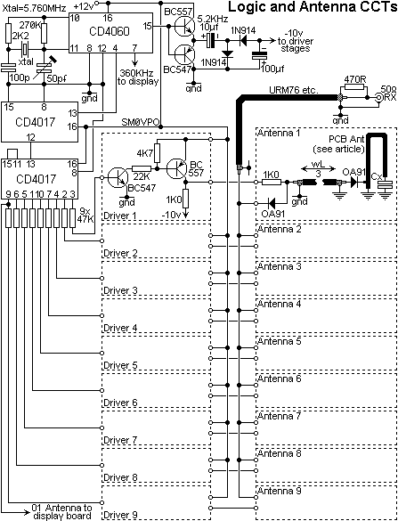
Description: If time and budget allow, consider enlarging this plate; a size of 5 meters would be ideal for a home base. This configuration resembles the systems used in modern aviation, where an antenna array modulates the phase of incoming signals. The commercial system is known as Commutated Aerial Direction Finding (CADF), which employs a ring of 18 identical antennas that are activated in sequence, similar to a rotary switch, ensuring that one antenna is always connected to the receiver.
If the receiver is positioned at the take-off point at the center of the array, any received signal will experience phase modulation, with the phase delay dependent on the signal's direction. For instance, if a signal originates from due North, Antenna-1 will receive signals that are part of one cycle ahead of the other antennas. As the commutator rotates, the signal fed to the receiver will increasingly lag in phase until Antenna-5 is activated. Continuing the rotation will cause the signal to lead again, resulting in a sinusoidal audio signal output from the receiver.
If the oscilloscope is triggered to start when Antenna-1 receives the signal, the waveform from the FM receiver will exhibit a specific pattern. If the incoming signal comes from due East, the received phase will advance until Antenna-3 is selected, then continue to lag again, with the greatest lag occurring when Antenna-7 is selected. The waveform will again lead after this point. Triggering the oscilloscope at Antenna-1 will display the waveform received from the FM receiver, which will reveal a 90-degree phase delay. By measuring the phase difference between the trigger point and the peak of the audio frequency wave, an accurate bearing to the target station can be determined.
In this project, the design of the antennas is critical, as they must be 100% identical to prevent phase discrepancies due to mis-tuning. The optimal solution is to utilize a folded 1/4-wave antenna, etched from copper-clad PCB fiberglass board, with a trimmer capacitor for frequency adjustment. Each antenna should be soldered onto an un-etched copper-clad board, which is then affixed to an aluminum or tin plate. A larger tin plate is preferable, with a diameter of 1000mm being suitable for operation at 144MHz or higher. A smaller plate would reduce the audio frequency output and compromise accuracy. The copper-clad board should be sufficiently sized to support one antenna and enable bolting to the tin plate, facilitating easy removal or repositioning of the antennas if necessary.
The antennas are arranged around the circumference of the metal plate, aligned along a line drawn from the center of the plate, with the 22p tuning capacitor oriented towards the edge. The angle between each antenna is precisely 40 degrees. In the prototype's diode switch circuit, a length of coaxial cable, a multiple of 33% of the wavelength (e.g., 670mm for 145MHz), was employed, with all terminations achieved by soldering the center core to a 2-pence coin and the tin plate. It may be beneficial to attach a piece of copper-clad board to the tin plate to simplify the termination of the coaxial cable.If you have the time and money then make this plate bigger, if possible. 5-meters would be ideal for a home base. Similar to the system used in modern aviation where an antenna array modulates the phase of an incoming signal. The commercial system is known as Commutated Aerial Direction Finding (CADF) where a ring of 18 identical antennas are each switched on in
sequence, just like winding a rotary switch round and round so that one antenna is always connected to the receiver. Consider: If the receiver is connected to the take-off point in the centre of the above diagram, then any received signal will become phase modulated, the phase delay being dependant upon the direction of the received signal.
Consider for one moment a signal comes from due North of the above array then Antenna-1 will receive signals that are part of one cycle in advance of all the other antennas. As the switch (commutator) is rotated then the signal fed to the receiver will gradually lag in phase more and more until Antenna -5 is selected.
Continuing the switch rotation round, the signal will again begin to lead. The overall effect will give us a sine (ish) audio signal out of the receiver. If we now triggered an oscilloscope so that the NORTH antenna made the trace start (the trailing edge of Antenna-9 switching pulse), then the waveform received from the FM receiver would look something like this (after filtering): If the station received now came from due East then as the antennas are switched the received phase would advance until Antenna-3 was selected then continue to lag again. The greatest lag would occur when Antenna-7 was selected then the signal would again begin to lead again.
If we still triggered the oscilloscope so that the NORTH antenna made the trace start, then the waveform received from the FM receiver would look something like this: As you can see, the waveform is delayed by exactly 90 degrees. By measuring the phase difference between the trigger point and the peak of the AF wave then we will therefore have an exact bearing to the target station.
In this project we shall be using the parameters: I had to develop an antenna since they should all be 100% identical without giving any phase changes by mis-tuning. The best method is to use a folded 1/4-wave antenna etched out of copper-clad PCB fibreglass board and using a trimmer capacitor to adjust the antenna frequency.
The antennas should each be soldered on a blank un-etched copper-clad board, which is then bolted to an aluminium or tin plate. The bigger the tin plate the better, but 1000mm Dia. will work for 144MHz or more. If it is too small then the AF output will be reduced and accuracy will suffer. The copper-clad board need only be large enough to support one antenna and allow it to be bolted to the tin plate.
This will allow the antennas to be easily removed or re-positioned, if it should become necessary. The antennas are mounted around the circumference of the metal plate, and aligned so that they are in-line with a line drawn from the centre of the plate and with the 22p tuning capacitor facing the edge of the plate. The angle between each antenna is exactly 40 °. A length of coaxial cable a multiple of 33% of the wavelength (145MHz = 670mm) was used on the prototype in the diode switch circuit and all were terminated by soldering the centre-core to a 2-pence coin and the tin plate.
You may wish to bolt a piece of copper-clad board to the tin plate so that it is easier to terminate the coaxial cable b
If the receiver is positioned at the take-off point at the center of the array, any received signal will experience phase modulation, with the phase delay dependent on the signal's direction. For instance, if a signal originates from due North, Antenna-1 will receive signals that are part of one cycle ahead of the other antennas. As the commutator rotates, the signal fed to the receiver will increasingly lag in phase until Antenna-5 is activated. Continuing the rotation will cause the signal to lead again, resulting in a sinusoidal audio signal output from the receiver.
If the oscilloscope is triggered to start when Antenna-1 receives the signal, the waveform from the FM receiver will exhibit a specific pattern. If the incoming signal comes from due East, the received phase will advance until Antenna-3 is selected, then continue to lag again, with the greatest lag occurring when Antenna-7 is selected. The waveform will again lead after this point. Triggering the oscilloscope at Antenna-1 will display the waveform received from the FM receiver, which will reveal a 90-degree phase delay. By measuring the phase difference between the trigger point and the peak of the audio frequency wave, an accurate bearing to the target station can be determined.
In this project, the design of the antennas is critical, as they must be 100% identical to prevent phase discrepancies due to mis-tuning. The optimal solution is to utilize a folded 1/4-wave antenna, etched from copper-clad PCB fiberglass board, with a trimmer capacitor for frequency adjustment. Each antenna should be soldered onto an un-etched copper-clad board, which is then affixed to an aluminum or tin plate. A larger tin plate is preferable, with a diameter of 1000mm being suitable for operation at 144MHz or higher. A smaller plate would reduce the audio frequency output and compromise accuracy. The copper-clad board should be sufficiently sized to support one antenna and enable bolting to the tin plate, facilitating easy removal or repositioning of the antennas if necessary.
The antennas are arranged around the circumference of the metal plate, aligned along a line drawn from the center of the plate, with the 22p tuning capacitor oriented towards the edge. The angle between each antenna is precisely 40 degrees. In the prototype's diode switch circuit, a length of coaxial cable, a multiple of 33% of the wavelength (e.g., 670mm for 145MHz), was employed, with all terminations achieved by soldering the center core to a 2-pence coin and the tin plate. It may be beneficial to attach a piece of copper-clad board to the tin plate to simplify the termination of the coaxial cable.If you have the time and money then make this plate bigger, if possible. 5-meters would be ideal for a home base. Similar to the system used in modern aviation where an antenna array modulates the phase of an incoming signal. The commercial system is known as Commutated Aerial Direction Finding (CADF) where a ring of 18 identical antennas are each switched on in
sequence, just like winding a rotary switch round and round so that one antenna is always connected to the receiver. Consider: If the receiver is connected to the take-off point in the centre of the above diagram, then any received signal will become phase modulated, the phase delay being dependant upon the direction of the received signal.
Consider for one moment a signal comes from due North of the above array then Antenna-1 will receive signals that are part of one cycle in advance of all the other antennas. As the switch (commutator) is rotated then the signal fed to the receiver will gradually lag in phase more and more until Antenna -5 is selected.
Continuing the switch rotation round, the signal will again begin to lead. The overall effect will give us a sine (ish) audio signal out of the receiver. If we now triggered an oscilloscope so that the NORTH antenna made the trace start (the trailing edge of Antenna-9 switching pulse), then the waveform received from the FM receiver would look something like this (after filtering): If the station received now came from due East then as the antennas are switched the received phase would advance until Antenna-3 was selected then continue to lag again. The greatest lag would occur when Antenna-7 was selected then the signal would again begin to lead again.
If we still triggered the oscilloscope so that the NORTH antenna made the trace start, then the waveform received from the FM receiver would look something like this: As you can see, the waveform is delayed by exactly 90 degrees. By measuring the phase difference between the trigger point and the peak of the AF wave then we will therefore have an exact bearing to the target station.
In this project we shall be using the parameters: I had to develop an antenna since they should all be 100% identical without giving any phase changes by mis-tuning. The best method is to use a folded 1/4-wave antenna etched out of copper-clad PCB fibreglass board and using a trimmer capacitor to adjust the antenna frequency.
The antennas should each be soldered on a blank un-etched copper-clad board, which is then bolted to an aluminium or tin plate. The bigger the tin plate the better, but 1000mm Dia. will work for 144MHz or more. If it is too small then the AF output will be reduced and accuracy will suffer. The copper-clad board need only be large enough to support one antenna and allow it to be bolted to the tin plate.
This will allow the antennas to be easily removed or re-positioned, if it should become necessary. The antennas are mounted around the circumference of the metal plate, and aligned so that they are in-line with a line drawn from the centre of the plate and with the 22p tuning capacitor facing the edge of the plate. The angle between each antenna is exactly 40 °. A length of coaxial cable a multiple of 33% of the wavelength (145MHz = 670mm) was used on the prototype in the diode switch circuit and all were terminated by soldering the centre-core to a 2-pence coin and the tin plate.
You may wish to bolt a piece of copper-clad board to the tin plate so that it is easier to terminate the coaxial cable b
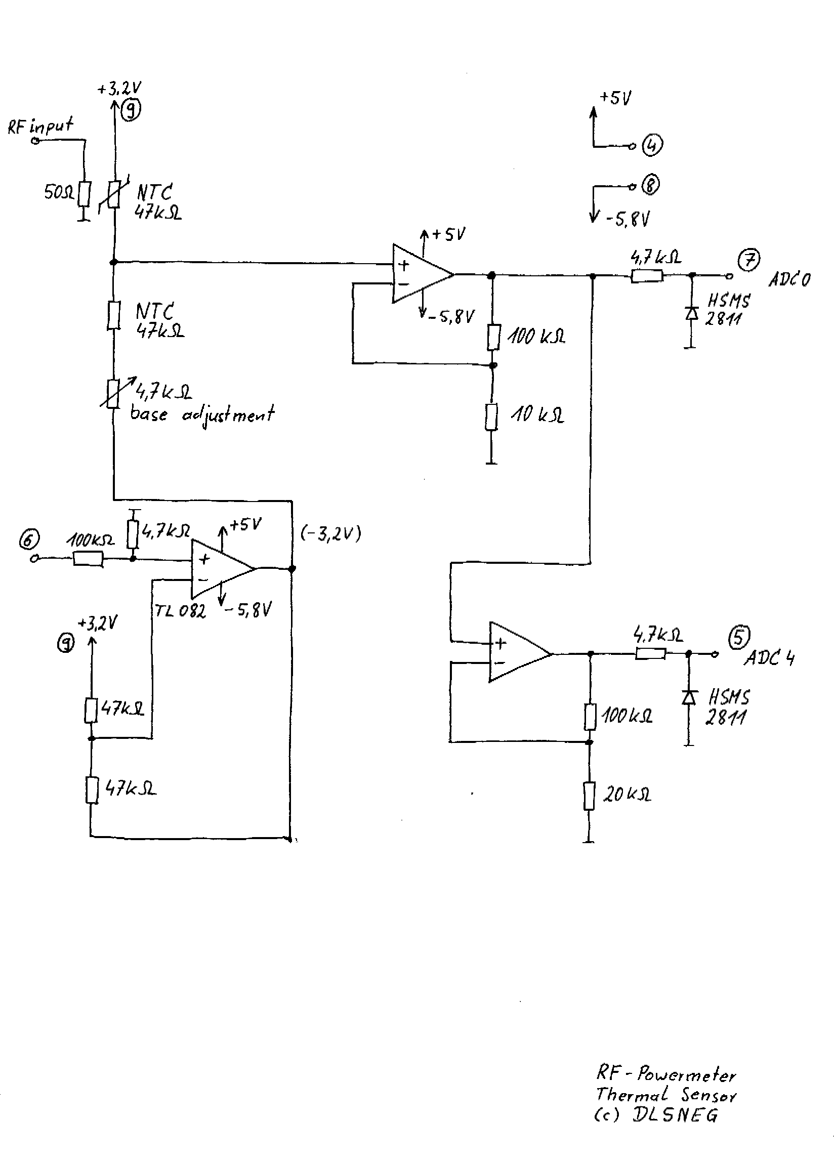
handheld RF-Powermeter for multiple sensors up to 12 GHz
A few years ago, a diode-sensor based RF power meter was built using a 68HC11 microprocessor. Prior to that, an analog RF power meter with a thermal power sensor was developed. The datasheets for logarithmic amplifiers, which promised a measurement...
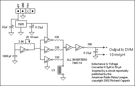
RF Inductance adaptor for multimeter
The circuit's operating principle is that if you make a pulse width proportional to inductance, and keep the pulse frequency and amplitude constant, and then pass the pulse through a low pass filter so that only the average voltage comes...
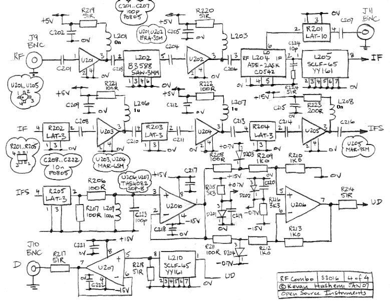
RF Combo
The RF Combo (A3016) integrates three circuits designed to support the development of circuit boards for Stage Four of a subcutaneous transmitter. The printed circuit board maintains the same outline as the RF Tester (A3014). The SAW Oscillator (A3016SO) replaces...
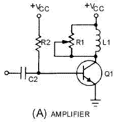
Armstrong Oscillator
The Armstrong oscillator is utilized to generate a sine-wave output with a constant amplitude and fairly stable frequency within the RF range. It is commonly employed as a local oscillator in receivers, as a source in signal generators, and as...
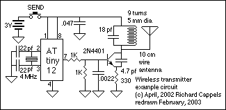
RF data link and remote control
This section describes an experimental low power, low bandwidth data signaling system that was initially made to operate at 55 MHz (television channel 2 in the U.S.). Before operating a radio transmitter, find out what kind of transmitter operation, if...
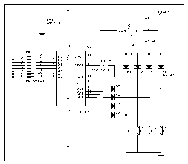
Four channel RF remote control
This is a simple RF transmitter circuit utilizing the Holtek HT-12E encoder chip and an AM 418MHz transmitter module (WZ-X01). The use of hybrid RF transmit/receive modules simplifies the construction of the RF remote control. The transmitter can operate with...
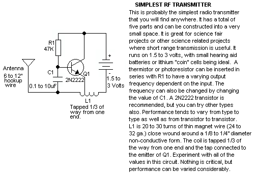
Simple RF Transmitter
This schematic represents a tone transmitter. When using sufficiently small resistor values, it generates a tone. A resistive microphone (such as a carbon microphone) can be placed in parallel with or replace the resistor, allowing modulation of the tone frequency...
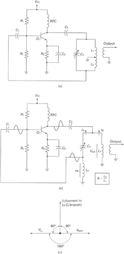
RF OSCILLATOR CIRCUITS
A widely recognized circuit is the Hartley oscillator, which is characterized by a tapped coil within the LC tank circuit. The tap point of the coil is grounded. The oscillator's amplifier section functions as a common-emitter amplifier, resulting in the...
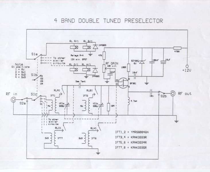
4 Band Double Tuned Preselector
The circuit requires an RF input, which can be sourced from either a long wire or a loop antenna. The preamplifier operates within a frequency range from 550 kHz (Medium Wave) up to 30 MHz in the shortwave band. The...