


DZ-2 CRV-46152 Aircraft Direction Finding Equipment
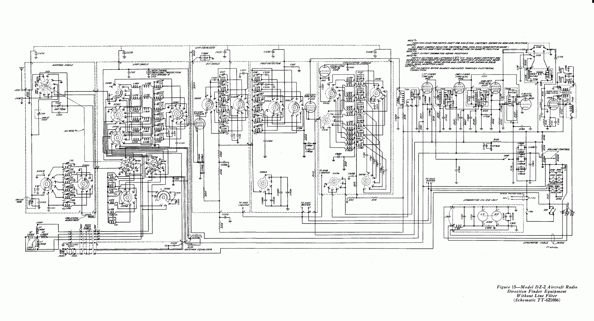
Description: The DZ-2 was developed by RCA in Camden, NJ, for the U.S. Navy to function as a Radio Direction Finder in naval aircraft. With a contract date of June 30, 1939, the receiver exemplifies pre-war design. It operates using the aircraft's 24V DC power system, with high tension (HT) supplied by a separate dynamotor. The receiver can also function without the direction-finding loop and is capable of tuning into Non-Directional Beacons (NDBs) as well as the entire AM Broadcast Band. The display receiver had undergone modifications by enthusiasts and suffered from inadequate storage conditions, having been subjected to high pressure in a shipping container for six years. The aluminum construction was adversely affected, necessitating extensive restoration work. As the dynamotor was unavailable and the filaments had been rewired for 6.3V AC previously, an external mains supply was utilized to provide power. A high tension of 250 volts is deemed satisfactory. The original output transformer, which only allowed for headphone output, was removed and replaced with a transformer capable of supporting both speaker and headphone outputs, in addition to a balanced 600-ohm line for museum use.
The DZ-2 Radio Direction Finder is a notable piece of electronic engineering, reflecting the technological capabilities of its era. Designed primarily for naval aviation, the receiver's architecture includes a robust 24V DC power system, ensuring reliable operation in demanding environments. The high tension (HT) supply, originally sourced from a dynamotor, was critical for the receiver's functionality, allowing it to achieve the necessary signal amplification for effective direction finding.
The ability to operate without the direction-finding loop broadens the receiver's utility, enabling it to cover the entire AM Broadcast Band and receive Non-Directional Beacon signals. This versatility makes the DZ-2 not only a specialized piece of equipment for military applications but also a valuable tool for general radio communication.
The restoration process highlights the importance of maintaining and preserving historical electronic equipment. The challenges faced due to prior modifications and adverse storage conditions underscore the need for careful handling of vintage electronics. The replacement of the original output transformer with a more versatile model capable of supporting both speaker and headphone outputs demonstrates a commitment to usability in a modern context, particularly for educational or display purposes in a museum setting.
Overall, the DZ-2 serves as a testament to early radio technology and its evolution, providing insights into the design considerations and engineering practices of the late 1930s. Its restoration and adaptation for contemporary use ensure that this piece of history remains accessible and functional for future generations.The DZ-2 was built by RCA, Camden NJ, for the U. S. Navy for use in naval aircraft as a Radio Direction Finder. With a contract date of June 30 1939, the receiver is an interesting example of pre-war design. The receiver was powered by the aircraft`s 24v DC power system, with the HT being provided by a separate dynamotor. The receiver can be used without the direction finding loop and covers the NDB`s and the whole AM Broadcast Band. The display receiver had suffered, firstly by some enthusiast`s modifications and secondly by being poorly stored and pressure cooked in a shipping container for 6 years. Aluminium does not like these conditions and the set needed quite a lot of restoration work. As the dynamotor was not available and the filaments had been rewired for 6. 3v AC in a previous life, an external mains supply was used to provide power. HT of 250 volts is satisfactory. The output transformer had been removed as it provided headphone output only. This was subsequently replaced with one capable of speaker and headphone output along with balanced 600 line for use in the museum.
The DZ-2 Radio Direction Finder is a notable piece of electronic engineering, reflecting the technological capabilities of its era. Designed primarily for naval aviation, the receiver's architecture includes a robust 24V DC power system, ensuring reliable operation in demanding environments. The high tension (HT) supply, originally sourced from a dynamotor, was critical for the receiver's functionality, allowing it to achieve the necessary signal amplification for effective direction finding.
The ability to operate without the direction-finding loop broadens the receiver's utility, enabling it to cover the entire AM Broadcast Band and receive Non-Directional Beacon signals. This versatility makes the DZ-2 not only a specialized piece of equipment for military applications but also a valuable tool for general radio communication.
The restoration process highlights the importance of maintaining and preserving historical electronic equipment. The challenges faced due to prior modifications and adverse storage conditions underscore the need for careful handling of vintage electronics. The replacement of the original output transformer with a more versatile model capable of supporting both speaker and headphone outputs demonstrates a commitment to usability in a modern context, particularly for educational or display purposes in a museum setting.
Overall, the DZ-2 serves as a testament to early radio technology and its evolution, providing insights into the design considerations and engineering practices of the late 1930s. Its restoration and adaptation for contemporary use ensure that this piece of history remains accessible and functional for future generations.The DZ-2 was built by RCA, Camden NJ, for the U. S. Navy for use in naval aircraft as a Radio Direction Finder. With a contract date of June 30 1939, the receiver is an interesting example of pre-war design. The receiver was powered by the aircraft`s 24v DC power system, with the HT being provided by a separate dynamotor. The receiver can be used without the direction finding loop and covers the NDB`s and the whole AM Broadcast Band. The display receiver had suffered, firstly by some enthusiast`s modifications and secondly by being poorly stored and pressure cooked in a shipping container for 6 years. Aluminium does not like these conditions and the set needed quite a lot of restoration work. As the dynamotor was not available and the filaments had been rewired for 6. 3v AC in a previous life, an external mains supply was used to provide power. HT of 250 volts is satisfactory. The output transformer had been removed as it provided headphone output only. This was subsequently replaced with one capable of speaker and headphone output along with balanced 600 line for use in the museum.
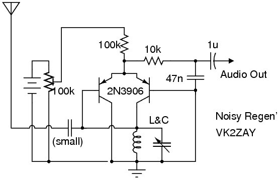
Noisy Regen Receiver
The following circuit illustrates a Noisy Regenerative Receiver Circuit Diagram. Features include a Noisy Regenerative Receiver Circuit, which simplifies the process of...
The Noisy Regenerative Receiver Circuit is designed to amplify weak radio frequency signals while also incorporating a regenerative feedback...
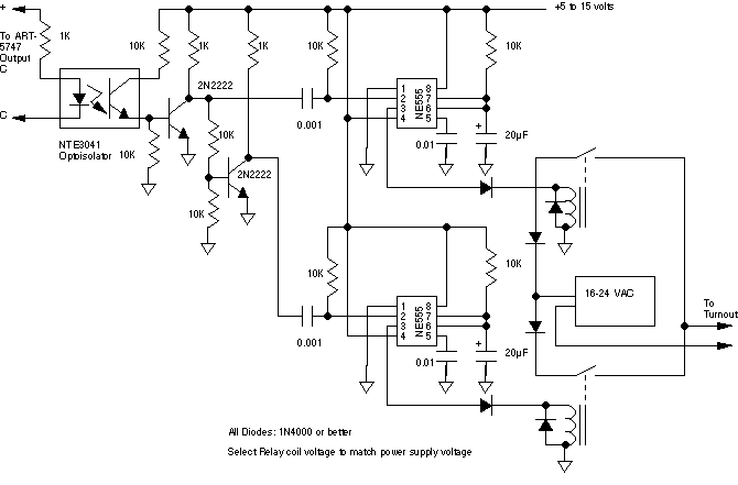
5474 tips
The Aristo ART-5474 Accessory Panel is a complete receiver designed to control accessories using buttons A through E on the Train Engineer transmitter. The ART-5474 is capable of controlling two turnouts, one constant load such as lights, and can trigger...
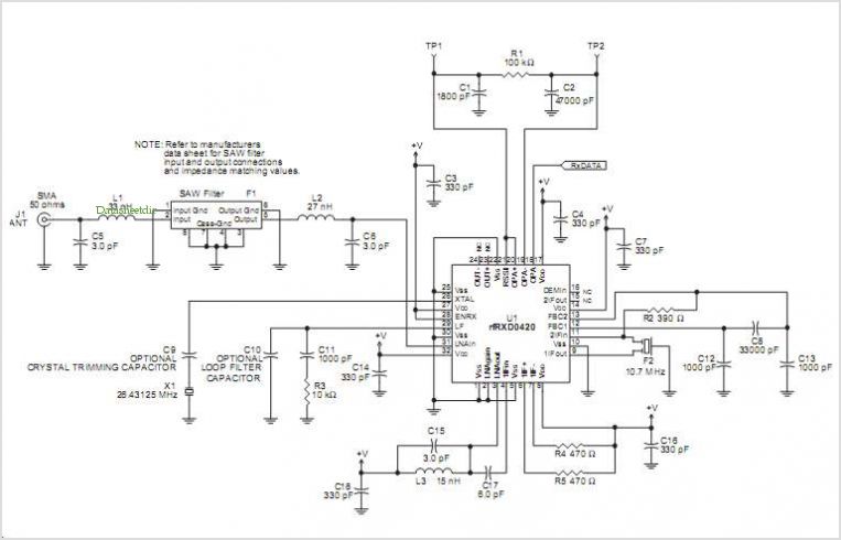
Rfrxd0420 Ask Receiver Reference Design
The RFRXD0420 and RFRXD0920 are low-cost, compact, single-frequency short-range radio receivers that require only a minimal number of external components for a complete receiver system. The RFRXD0420 operates within the frequency range of 300 MHz to 450 MHz, while the...
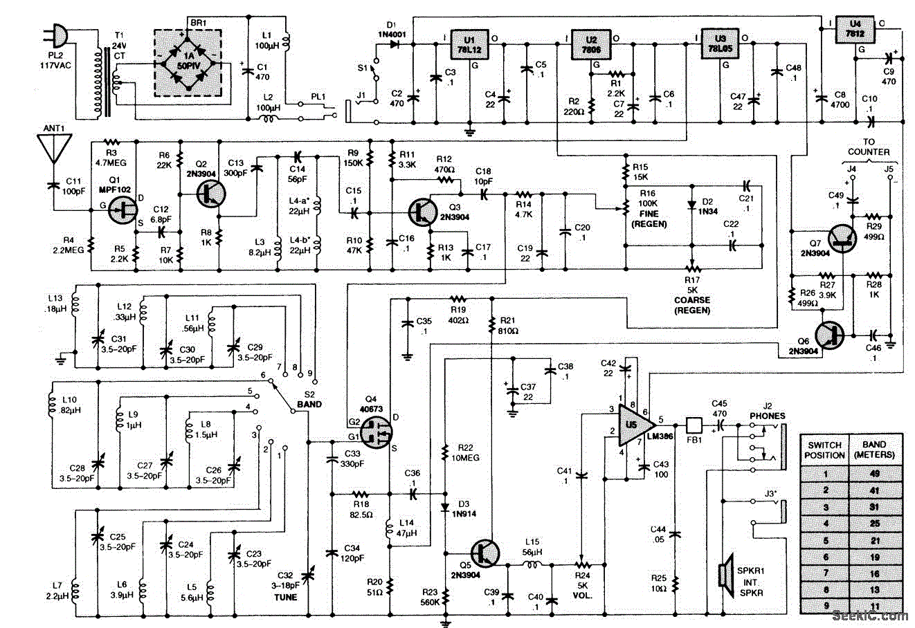
REGENERATIVE_SHORTWAVE_RECEIVER
The receiver consists of multiple subassemblies, including an active antenna, an amplifier featuring regeneration control and band-switching circuitry, an AM detector, a power amplifier, and an output device such as an internal speaker, external speaker, or headphones. Additionally, it is...
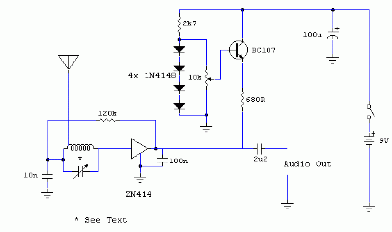
MK414 SW Receiver
The original data sheet for the MK414 indicates that the maximum working frequency is approximately 4 MHz. SW transmissions are sufficiently strong that this receiver can effectively operate with signals up to about 6 or 7 MHz. A 10k resistor...
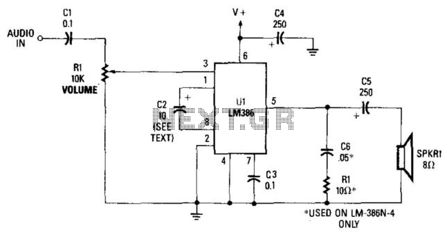
Receiver Audio Circuit
This simple receiver AF amplifier can supply several hundred milliwatts to an 8-ohm speaker. The gain is approximately 200X. If high gain is not required, C2 can be removed, resulting in a gain of 20. R1 and C6 are essential...
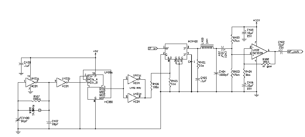
136 kHz QRSS receiver
For digital modes, the ideal receiver should be straightforward, featuring front-end selectivity, manually adjustable gain, and an IF filter. Many functionalities found in HF receivers can be implemented through software. In the collection of components, there was a surplus 1.4...
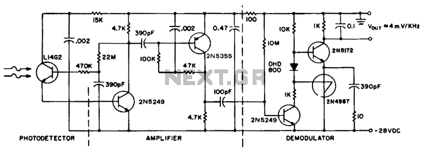
Receiver for 50 khz optical transmitter
To achieve maximum range, the receiver should be constructed similarly to a radio receiver front end, as the signals received will exhibit comparable frequency components and amplitudes of the photodiode current. The primary limitation on the receiver's performance is the...
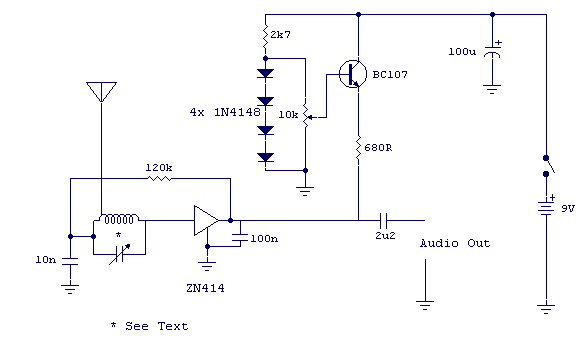
SW Receiver Using MK414
The tuned circuit consists of a variable capacitor and fixed air spaced coil. For the coil, wound between 10 and 20 turns of wire on an empty tube of around 1.5 inches diameter. The turns were spaced so that the...