


FM IF Subsystem with CA3189E
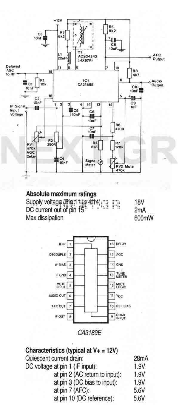
Description: The CA3189E is a comprehensive FM-IF system designed for high fidelity FM tuners. It includes a three stage FM-IF amplifier/limiter configuration with level detectors for each stage, a double-balanced quadrature FM detector and an audio amplifier that features the optional use of a muting circuit. The advanced circuit design includes desirable special features such as delayed AGC for the RF tuner, an AFC drive circuit, and an output signal to drive a tuning meter and/or provide stereo switching logic. In addition, internal power supply regulators maintain a nearly constant current drain over the voltage supply range of +8V to +16V. Distortion is primarily a function of the phase linearity characteristics of the external detector coil. More: Features: 1. Exceptional limiting sensitivity: 10uV (typical) at -3dB 2. Low distortion: 0.1% (with double-tuned coil) typical 3. Single coil tuning capability. 4. High recovered audio: 500mV (typical). 5. Internal supply-voltage regulators. 6. AGC threshold.
The CA3189E integrated circuit is engineered for high-performance FM demodulation and is particularly suited for high-fidelity FM tuners. The architecture consists of a three-stage FM intermediate frequency (IF) amplifier and limiter, which enhances the signal-to-noise ratio and ensures clean audio output. Each amplification stage is equipped with level detectors that monitor and maintain signal integrity throughout the amplification process.
A notable feature of the CA3189E is its double-balanced quadrature FM detector. This configuration significantly reduces distortion and enhances the fidelity of the recovered audio signal. The audio amplifier section is capable of producing a high output level, typically around 500mV, ensuring compatibility with various audio processing stages. An optional muting circuit can be integrated into the design to eliminate unwanted noise during tuning, enhancing user experience.
The circuit design incorporates delayed automatic gain control (AGC), which stabilizes the gain of the RF tuner and prevents distortion during sudden changes in signal strength. The addition of an AFC (automatic frequency control) drive circuit allows for fine-tuning of the received frequency, improving overall tuning accuracy. The output signal can be utilized to drive a tuning meter or facilitate stereo switching logic, adding versatility to the tuner’s operation.
Power management is efficiently handled by internal supply-voltage regulators, which maintain stable operation across a voltage supply range of +8V to +16V. This feature ensures that the circuit operates reliably under varying power conditions, while also keeping current drain consistent, thus optimizing performance.
The CA3189E is characterized by exceptional limiting sensitivity, with a typical threshold of 10µV at -3dB, making it suitable for weak signal reception. The low distortion rate of 0.1% with a double-tuned coil further emphasizes its capability for high-quality audio reproduction. Additionally, the single-coil tuning capability simplifies the design and reduces component count, enhancing reliability and ease of integration into existing systems. Overall, the CA3189E represents a sophisticated solution for high-fidelity FM tuning applications, combining advanced features with robust performance.TheCA3189E is a comprehensive FM-IF system designed for high fidelity FM tuners. It includes a three stage FM-IF amplifier/limiter configuration with level detectors for each stage, a double-balanced quadrature FM detector and an audio amplifier that features the optional use of a muting circuit. The advanced circuit design includes desirable special features such as delayed AGC for the RF tuner, an AFC drive circuit, and an output signal to drive a tuning meter and/or provide stereo switching logic.
In addition, internal power supply regulators maintain a nearly constant current drain over the voltage supply range of +8V to +16V. Distortion is primary a function of the phase linearity characteristics of the external detector coil.
Features: 1.Exceptional limiting sensitivity :10uV(typical) at -3dB 2.Low distortion: 0.1% (with double-tuned coil) typical 3. Single coil tuning capability. 4. High recovered audio: 500mV (typical). 5. Internal supply-voltage regulators. 6. AGC threshol
The CA3189E integrated circuit is engineered for high-performance FM demodulation and is particularly suited for high-fidelity FM tuners. The architecture consists of a three-stage FM intermediate frequency (IF) amplifier and limiter, which enhances the signal-to-noise ratio and ensures clean audio output. Each amplification stage is equipped with level detectors that monitor and maintain signal integrity throughout the amplification process.
A notable feature of the CA3189E is its double-balanced quadrature FM detector. This configuration significantly reduces distortion and enhances the fidelity of the recovered audio signal. The audio amplifier section is capable of producing a high output level, typically around 500mV, ensuring compatibility with various audio processing stages. An optional muting circuit can be integrated into the design to eliminate unwanted noise during tuning, enhancing user experience.
The circuit design incorporates delayed automatic gain control (AGC), which stabilizes the gain of the RF tuner and prevents distortion during sudden changes in signal strength. The addition of an AFC (automatic frequency control) drive circuit allows for fine-tuning of the received frequency, improving overall tuning accuracy. The output signal can be utilized to drive a tuning meter or facilitate stereo switching logic, adding versatility to the tuner’s operation.
Power management is efficiently handled by internal supply-voltage regulators, which maintain stable operation across a voltage supply range of +8V to +16V. This feature ensures that the circuit operates reliably under varying power conditions, while also keeping current drain consistent, thus optimizing performance.
The CA3189E is characterized by exceptional limiting sensitivity, with a typical threshold of 10µV at -3dB, making it suitable for weak signal reception. The low distortion rate of 0.1% with a double-tuned coil further emphasizes its capability for high-quality audio reproduction. Additionally, the single-coil tuning capability simplifies the design and reduces component count, enhancing reliability and ease of integration into existing systems. Overall, the CA3189E represents a sophisticated solution for high-fidelity FM tuning applications, combining advanced features with robust performance.TheCA3189E is a comprehensive FM-IF system designed for high fidelity FM tuners. It includes a three stage FM-IF amplifier/limiter configuration with level detectors for each stage, a double-balanced quadrature FM detector and an audio amplifier that features the optional use of a muting circuit. The advanced circuit design includes desirable special features such as delayed AGC for the RF tuner, an AFC drive circuit, and an output signal to drive a tuning meter and/or provide stereo switching logic.
In addition, internal power supply regulators maintain a nearly constant current drain over the voltage supply range of +8V to +16V. Distortion is primary a function of the phase linearity characteristics of the external detector coil.
Features: 1.Exceptional limiting sensitivity :10uV(typical) at -3dB 2.Low distortion: 0.1% (with double-tuned coil) typical 3. Single coil tuning capability. 4. High recovered audio: 500mV (typical). 5. Internal supply-voltage regulators. 6. AGC threshol
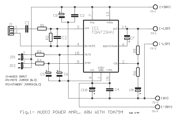
Audio Power Amplifier 60W with TDA7294 circuit
The TDA7294 amplifier module is a monolithic integrated circuit designed for use as a Class AB audio amplifier in high-fidelity applications. It features a wide voltage range and output current capability, allowing it to deliver high power to both 4-ohm...
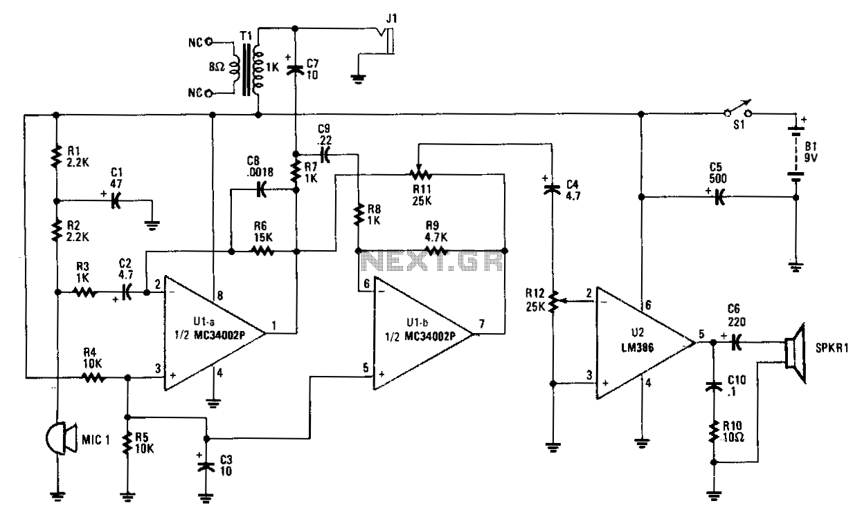
Hands-off-intercom
Amplifier A increases the microphone's output to a usable level. The output signal is fed to op amp B, which inverts the signal by 180 degrees. A balance-control potentiometer connects across the outputs of amplifiers A and B. If an...
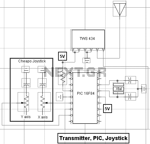
Building an RF Remote Control System For Robotics Control
With a handful of inexpensive components, a little creativity, and the power of PicBasic, you can build some pretty outstanding robotics creations as Rob Arnold proves with his Ruf-Bot project. RF remote control is just way too cool not to...
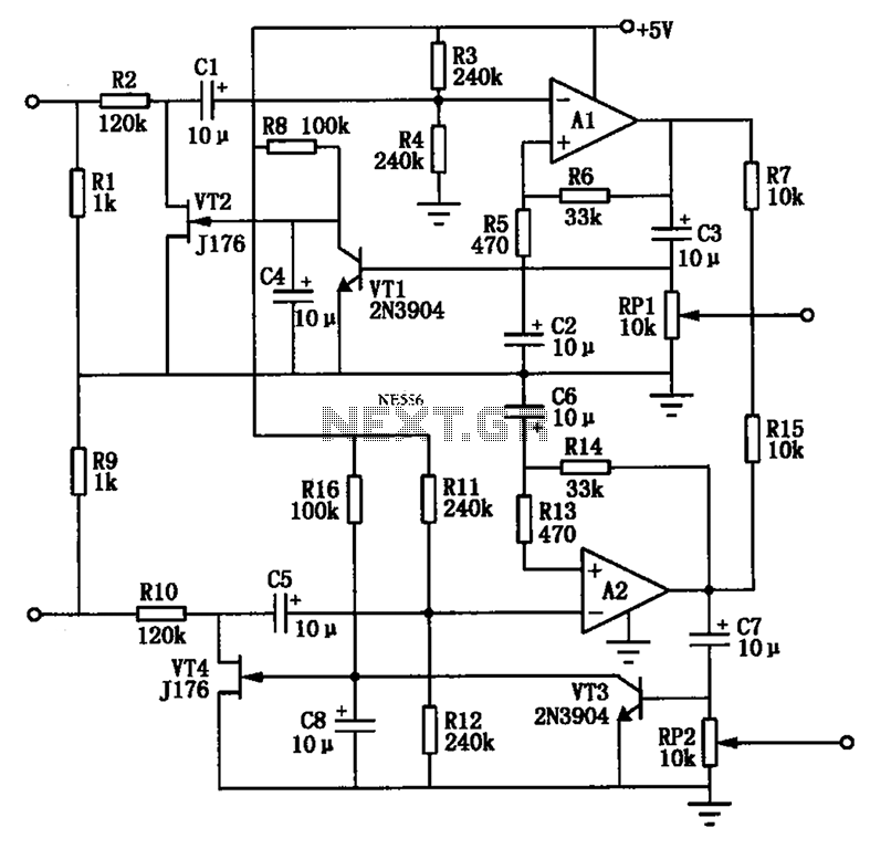
Audio AGC amplifier circuit
The Audio Automatic Gain Control (AGC) circuit monitors the output signal level of an audio preamplifier. When the input signal increases, the AGC circuit automatically reduces the amplifier's gain. Conversely, when the input signal decreases, the AGC circuit increases the...
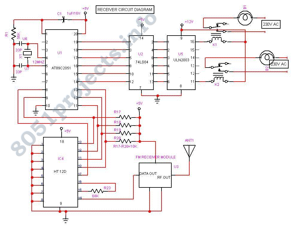
RF Remote control
The Project Long Range Remote Control can be used to remotely control a number of Electrical or Electronic Gadgets connected to it. Unlike Infra Red remote control, this Project employs FM transmission and Reception, and hence it can be used...
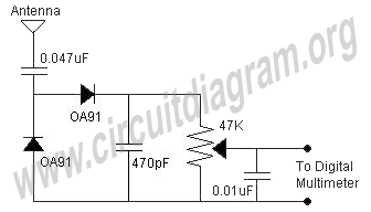
field strength meter fsm
A field strength meter circuit is a valuable device for measuring the RF output of any transmitter or for experimenting with different antennas connected to the transmitter. The operation of the field strength meter (FSM) is straightforward; it converts RF...
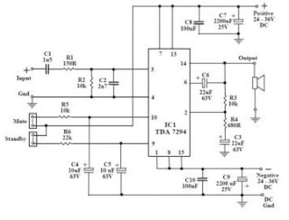
amplifier circuit
This audio amplifier circuit utilizes the TDA7294, a power integrated circuit designed for high-quality audio applications. The TDA7294 operates as a class AB amplifier, characterized by low noise and distortion levels, a wide bandwidth, and robust output current capability. It...
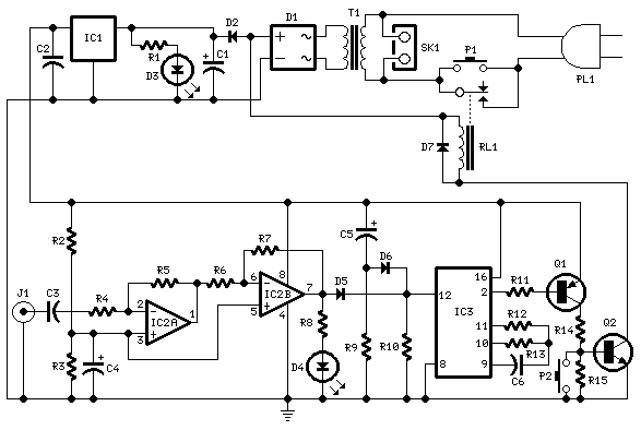
Amplifier Timer
This circuit deactivates an amplifier or other devices when a low-level audio signal at its input is absent for at least 15 minutes. By pressing P1, the device is activated, supplying power to any appliance connected to SK1. The input...
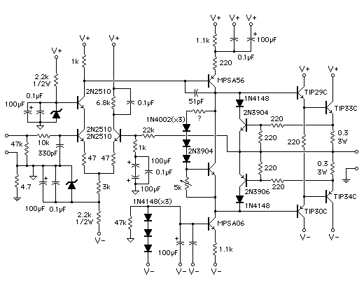
Audio Power Amplifier
Measure the voltage across the 1k resistor connected to the input stage and Vcc. The DC voltage should be approximately 2 volts, or 2 mA of current flowing through this resistor. For instance, if Vcc is at 24 volts, the...