


Frequency Modulator and Tuning Circuit
#frequency modulator
#tuning circuit
#varactor diodes
#1N4007
#xtal circuit
#RF design
#signal modulation
#oscillator
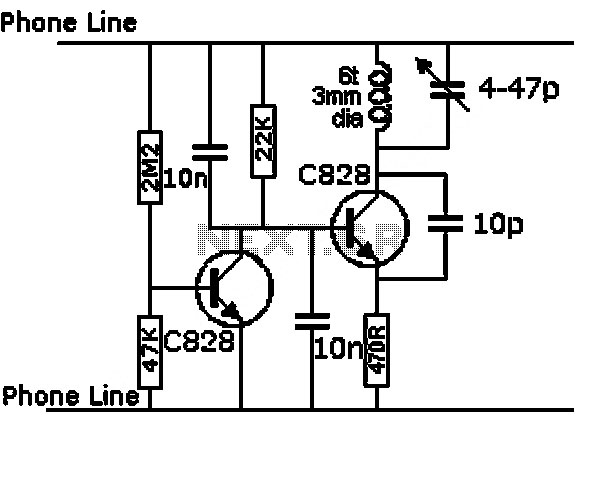
Description: Here is a design circuit for a frequency modulator that is equipped with a tuning circuit. In this circuit, a pair of 1N4007 diodes is utilized as varactor diodes. The choice of 1N4007 diodes is not due to their specific suitability but rather because they were available. One of the varactors is directly coupled to the crystal circuit through a 1 nF capacitor, allowing for most of its capacitance change to be observed. The other varactor is coupled via a small trimmer to fine-tune its maximum effect. This configuration provides two independent channels: one for relatively coarse frequency tuning and the other for frequency-shift keying (FSK) modulation. The circuit data exhibits a characteristically parabolic shape, as expected. Any irregularities in the fine trace may be attributed to measurement errors. The y-coordinates are in Hz relative to 10.138000 MHz, with x representing reverse voltage, indicating that minor measurement inaccuracies can cause the fine trace to appear uneven.
The frequency modulator circuit utilizes a pair of 1N4007 diodes configured as varactor diodes, which are essential for voltage-controlled capacitance. In this application, one varactor is directly connected to the crystal oscillator circuit through a 1 nF capacitor, allowing for significant changes in capacitance to influence the oscillator frequency. This direct coupling ensures that the frequency modulation is responsive and effective, as the capacitance variation directly affects the oscillation frequency.
The second varactor is coupled through a small trimmer capacitor, which enables precise adjustments to maximize its effect on the modulation process. This dual-channel approach allows for a coarse tuning mechanism alongside a fine-tuning option, facilitating both broad frequency adjustments and more delicate frequency-shift keying (FSK) modulation.
The overall design results in a frequency modulation output that can be characterized by a parabolic response curve, which is typical for such circuits. The parabolic nature of the data indicates the relationship between reverse voltage applied to the varactor diodes and the resulting frequency changes. However, it is important to note that any anomalies in the data, particularly in the fine-tuning trace, may arise from measurement errors, emphasizing the need for careful calibration and measurement techniques.
In summary, this frequency modulator circuit effectively employs varactor diodes to achieve tunable frequency modulation, with a robust design that allows for both coarse and fine adjustments, suitable for various applications in communication systems where frequency stability and modulation accuracy are paramount.Here`s a design circuit for frequency modulator that is completed with tuning circuit. In this circuit is using pair of 1N4007s are used as varactor diodes. I picked 1N4007s not because they are particularly well suited, but simply that I had some on the bench. One of the varactors is directly coupled to the xtal circuit through 1 nF so most of it s capacitance change is seen, the other is coupled through a small trimmer to adjust its maximum effect. This gives two independent channels, one for relatively coarse frequency tuning, the other for FSK modulation.
Here`s the figure of the circuit; The data looks characteristically parabolic as expected. I suspect the oddness of the fine is measurement error. The y coordinates are in Hz relative to 10. 138000 MHz (x is reverse voltage) so it doesn`t take much error in measurement to make the fine trace look lumpy.
The frequency modulator circuit utilizes a pair of 1N4007 diodes configured as varactor diodes, which are essential for voltage-controlled capacitance. In this application, one varactor is directly connected to the crystal oscillator circuit through a 1 nF capacitor, allowing for significant changes in capacitance to influence the oscillator frequency. This direct coupling ensures that the frequency modulation is responsive and effective, as the capacitance variation directly affects the oscillation frequency.
The second varactor is coupled through a small trimmer capacitor, which enables precise adjustments to maximize its effect on the modulation process. This dual-channel approach allows for a coarse tuning mechanism alongside a fine-tuning option, facilitating both broad frequency adjustments and more delicate frequency-shift keying (FSK) modulation.
The overall design results in a frequency modulation output that can be characterized by a parabolic response curve, which is typical for such circuits. The parabolic nature of the data indicates the relationship between reverse voltage applied to the varactor diodes and the resulting frequency changes. However, it is important to note that any anomalies in the data, particularly in the fine-tuning trace, may arise from measurement errors, emphasizing the need for careful calibration and measurement techniques.
In summary, this frequency modulator circuit effectively employs varactor diodes to achieve tunable frequency modulation, with a robust design that allows for both coarse and fine adjustments, suitable for various applications in communication systems where frequency stability and modulation accuracy are paramount.Here`s a design circuit for frequency modulator that is completed with tuning circuit. In this circuit is using pair of 1N4007s are used as varactor diodes. I picked 1N4007s not because they are particularly well suited, but simply that I had some on the bench. One of the varactors is directly coupled to the xtal circuit through 1 nF so most of it s capacitance change is seen, the other is coupled through a small trimmer to adjust its maximum effect. This gives two independent channels, one for relatively coarse frequency tuning, the other for FSK modulation.
Here`s the figure of the circuit; The data looks characteristically parabolic as expected. I suspect the oddness of the fine is measurement error. The y coordinates are in Hz relative to 10. 138000 MHz (x is reverse voltage) so it doesn`t take much error in measurement to make the fine trace look lumpy.
Minimal metal detector
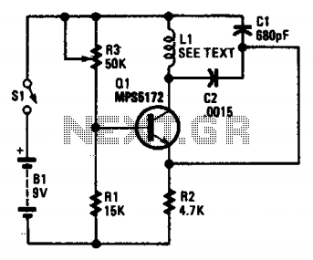
This circuit is an oscillator with LI being a 4-inch diameter coil consisting of 35 turns of #26 magnet wire. Metal in proximity to LI will cause the oscillator to shift frequency. An AM transistor radio is used to detect...
High-current-oscillator
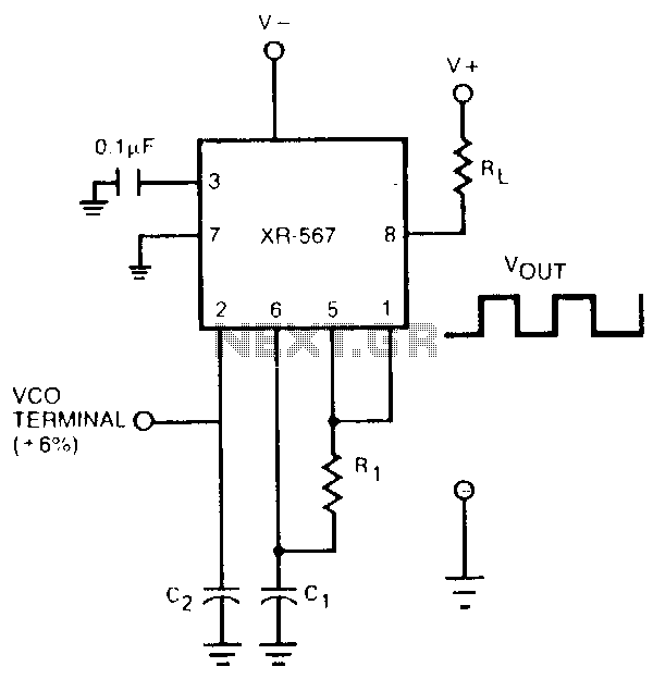
The oscillator output of the XR-567 can be amplified using the output amplifier and high-current logic output available at pin 8. In this manner, the circuit can switch 100-mA load currents without sacrificing oscillator stability. The oscillator frequency can be...
Electronic Organ Circuit
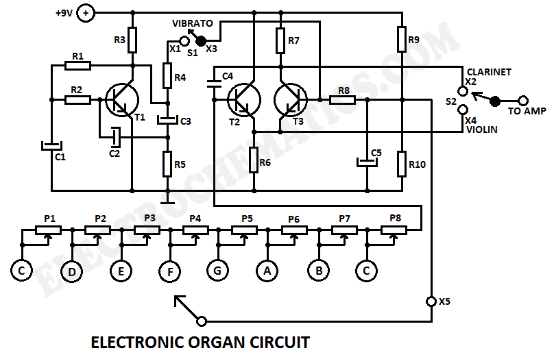
This electronic organ circuit is straightforward to construct and primarily consists of an emitter-coupled oscillator formed by transistors T2 and T3. A square wave voltage can be obtained from the collector of T3 (X2), which imparts a clarinet-like quality to...
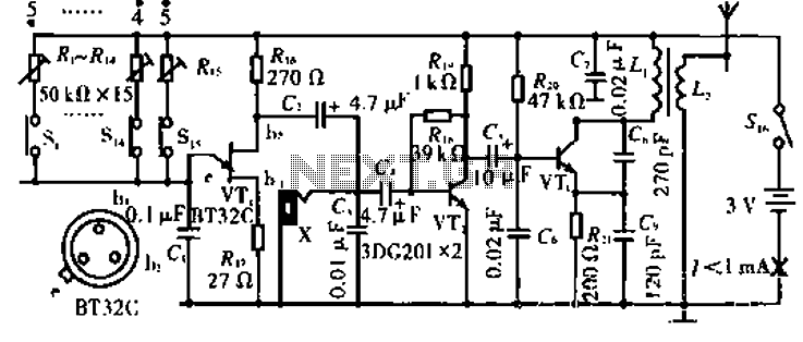
Wireless keyboard circuit
The circuit operates with VT3 and associated components arranged as a common-base capacitance feedback oscillation circuit. The oscillation frequency is set by capacitors C8, C9, and inductor L1. VT2 serves as a voltage amplification stage that reinjects the audio signal...
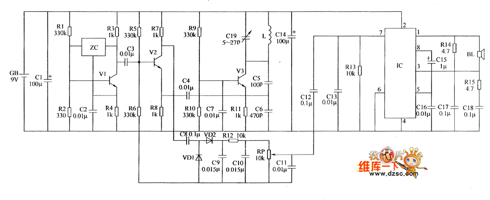
Metal detector circuit diagram 1
The metal detector circuit includes a fixed frequency oscillator, mixer, detector, detection oscillator, and power amplifier circuit. The fixed frequency oscillator circuit is composed of a ceramic filter (ZC), transistor (V1), resistors (R1 to R4), capacitor (C2), and other components....
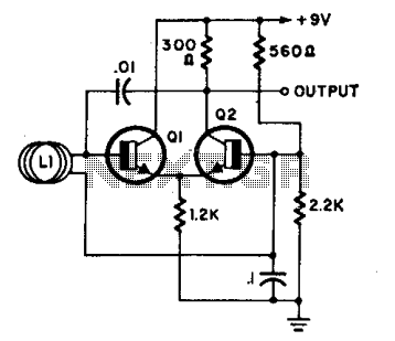
Big loop oscillator
L1 is a loop consisting of 10 to 20 turns of insulated wire with a diameter ranging from 4 inches to 4 feet. The oscillator frequency, which operates between 7 to 30 MHz, varies significantly when an individual approaches or...
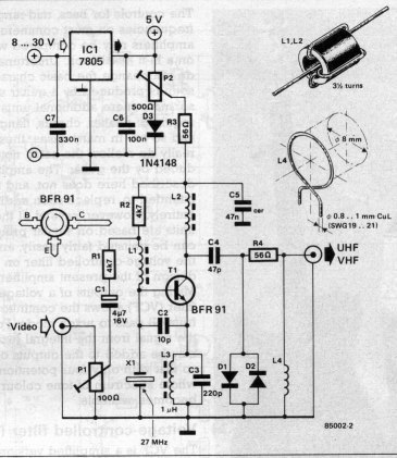
VHF/UHF TV Modulator
A simple oscillator generates a frequency in the VHF or UHF range. This oscillator is modulated with a video signal, and the resulting modulated carrier wave is transmitted to the TV set's aerial input through a cable. The final step...
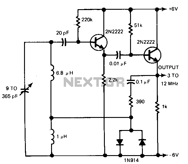
Wide-range-oscillator
The gain control enables the oscillator to maintain a nearly constant output across its range. The circuit operates within a frequency range of 160 kHz to 12 MHz while producing a consistent amplitude.
The oscillator circuit described utilizes a gain control...
VHF/UHF TV Modulator
A simple oscillator generates a frequency in the VHF or UHF range. This oscillator is modulated with a video signal, and the resulting modulated carrier wave is transmitted to the TV set's aerial input through a cable. The final step...