


From Crystal Sets To 405 Line television
#valve radio
#tuned circuit
#inductor
#capacitor
#high frequency amplification
#detection
#audio amplification
#radio receiver
#RF signal
Description: A valve radio receiver, in its simplest form, consists of a frequency-determining tuned circuit made up of an inductor and capacitor in parallel, followed by a series of valves connected together. These valves amplify the signal, perform detection (rectification), and provide low-frequency amplification (audio amplification). A loudspeaker or headphones serve as the output for the valve chain. There are various methods to link the separate valves, which will be illustrated. In the basic arrangement, a resistor (Ra) is placed between the anode of Valve A and the high tension (H.T) supply. The alternating current (A.C) signal from Valve A's anode is transmitted to Valve B through a capacitor (C) that must withstand the H.T supply voltage. If this capacitor fails, the grid of Valve B could be exposed to damaging H.T voltage from Valve A's anode. Resistor Rb acts as a grid leak resistor, providing a path for electrons from Valve B's grid. The capacitance of C is selected to ensure low impedance for the signal being processed. Resistance-capacitance coupling is suitable only for audio frequencies (20 Hz to 20 kHz); at higher frequencies, capacitive effects within the valve reduce the gain from the coupled stages. An alternative arrangement replaces the resistor between the first valve's anode and the H.T voltage with an inductor (choke). The values of the inductor and capacitor depend on the desired operating frequency and the impedance of Valve B's input circuit. This setup requires a transformer (TR1) capable of handling the anode current from Valve A without significant distortion. The transformer prevents the high tension D.C. voltage on Valve A's anode from reaching Valve B's grid, as transformers only transmit varying signals between their primary and secondary windings. This configuration is a simple valve amplifier stage, akin to the amplifier discussed in a previous chapter, but with the anode resistor replaced by a parallel tuned circuit. Often, the inductive element is the primary of a coupling transformer, and the secondary may also be tuned with a capacitor. A tuned amplifier maximizes impedance at a specific frequency, enhancing the varying signal at the anode while unwanted frequencies experience low impedance, thus not appearing at the valve anode. Variable capacitors (Vc1 and Vc2) allow for tuning the circuit frequency. Tuned circuits are advantageous at high frequencies, as any inherent stray capacitance in the valve or wiring contributes to the tuned circuit's capacitive element, maintaining amplifier performance. An oscillator generates a varying waveform from a steady D.C. In radio receivers, oscillators typically produce sine waves at radio frequencies (R.F.) and incorporate an LC tuned circuit. They utilize positive feedback, where a portion of the amplifier's output is fed back to the input, increasing amplifier gain. For effective positive feedback, the feedback signal must be in phase with the input signal. A Colpitts Oscillator circuit is illustrated, featuring an LC tuned circuit composed of Vc1, L1, C1, and C2, which connects the amplifier output (V1 Anode) to its input.
The valve radio receiver operates by utilizing a tuned circuit to selectively amplify specific frequencies from incoming radio signals. The tuned circuit, composed of an inductor and capacitor, resonates at a particular frequency, allowing the receiver to filter out unwanted signals and focus on the desired broadcast frequency. The valves, or vacuum tubes, serve as active components that amplify the weak signals captured by the antenna. The arrangement of valves in series enhances the overall gain and facilitates the detection of audio signals embedded within the radio frequency.
The coupling between valves can be achieved through various methods, including capacitive and inductive coupling, each having its advantages and limitations. Capacitive coupling is straightforward and allows for easy signal transfer; however, it is limited to audio frequencies due to the capacitive effects that become significant at higher frequencies. Inductive coupling, on the other hand, can handle a broader range of frequencies and is often employed in tuned circuits to maintain signal integrity.
The use of transformers in the coupling process is crucial, as they isolate the high voltage from the anode of the first valve from the grid of the subsequent valve, preventing potential damage. The transformer also enables impedance matching, which is essential for maximizing power transfer between stages. The tuned amplifier configuration enhances the selectivity and sensitivity of the receiver, ensuring that only the desired frequencies are amplified, while unwanted signals are effectively suppressed.
Variable capacitors in the tuned circuit allow for fine-tuning of the receiver to different frequencies, accommodating various radio stations. The oscillator circuit, such as the Colpitts type, plays a vital role in generating the carrier wave necessary for modulation and demodulation processes. By implementing positive feedback, the oscillator maintains a stable output frequency, ensuring that the receiver can effectively process the incoming signals.
In summary, the valve radio receiver exemplifies classic analog signal processing techniques, utilizing tuned circuits, valves, and transformers to achieve selective amplification and signal detection. This fundamental understanding of the circuit design and operation is essential for anyone working with or studying vintage radio technology.A valve radio receiver in its crudest form is a frequency determining tuned circuit, (consisting of an inductor and capacitor in parallel) followed by a series of valves coupled together. These valves act on the signal and provide high frequency amplification, detection (rectification) and low frequency amplification (audio amplification).
A louds peaker or headphones terminates the line of valves. There are several ways in which linkage can be provided between the separate valves; the basic methods will now be shown. This arrangement is shown in Figure 3a. There is a resistor (Ra) between Valve A`s anode and the H. T supply. The A. C signal on the anode of valve A is passed to valve B via capacitor C, which should be well able to withstand the H.
T supply voltage. In the event of a breakdown of this component, the grid of Valve B would be exposed to damaging H. T voltage from Valve A`s anode. Resistor Rb is to provide a path for electrons from the grid of valve B (the so-called grid leak resistor). The capacitance value of C is chosen to present low impedance to the signal to be processed. Resistance - Capacitance coupling is only suitable for use at audio frequencies (20Hz-20 KHz); above these frequencies capacitive effects in the valve reduces the gain possible from the coupled stages.
This arrangement follows the form of the capacitive-resistive coupling illustrated in diagram 3a but the resistor between the first valve`s anode and the H. T voltage is replaced by an inductor (choke). The inductor and Capacitor values will depend on the frequency that the stage is required to operate at and the impedance of Valve B`s input circuit.
This is arrangement is shown in figure 3b. It requires the use of a transformer (TR1) that is able to withstand the anode current from the first Valve A flowing through the primary without its inductance being badly effected (potentially resulting in distortion). The high tension D. C voltage on Valve A`s anode is prevented from reaching Valve B`s grid by the transformer (transformers pass only moving signal between their primary and secondary windings.
This is usually a simple valve amplifier stage, similar to the amplifier discussed in Chapter 2 but with the anode resistor being replaced with a parallel tuned circuit (see chapter 1). Often the inductive element is the primary of a coupling transformer, the secondary of the transformer may also be tuned with a capacitor.
A tuned amplifier is shown in figure 3c. It has to be understood that as far as a varying voltage is concerned, any steady D. C voltage (such as the H. T supply) is regarded as "earth". This makes the tuned amplifier easier to understand. At a specific frequency, the impedance of the tuned circuit is maximised and the varying signal at the anode will be maximised. Other (unwanted) frequencies will see the tuned circuit as low impedance and hence will not appear at the valve anode.
Variable capacitors Vc1 and Vc2 allow the frequency to which the circuit is tuned to be altered. Tuned circuits are useful at high frequencies because any "inherent" (stray) capacitance present in the valve or wiring will in form part of the capacitive element of the tuned circuit and not degrade the performance of the amplifier. An oscillator is a device that produces a varying waveform from a steady D. C. In a radio receiver they usually produce sine waves, at radio frequency (R. F), oscillators generally incorporate an LC tuned circuit. Oscillators utilise an effect known as positive feedback. Positive feedback is when a sample of an amplifier ’s output is added to the input; the effect of this is to increase the gain of the amplifier.
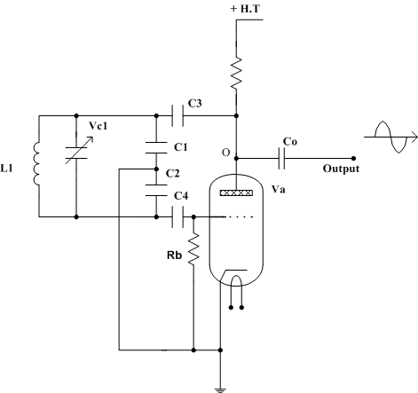
For positive feedback to occur, the feedback signal must be in phase with the applied signal. Figure 3d shows a Colpitts Oscillator circuit. An LC tuned circuit comprising Vc1, L1, C1, C2 provides a path between an amplifier output (V1 Anode) and its input
The valve radio receiver operates by utilizing a tuned circuit to selectively amplify specific frequencies from incoming radio signals. The tuned circuit, composed of an inductor and capacitor, resonates at a particular frequency, allowing the receiver to filter out unwanted signals and focus on the desired broadcast frequency. The valves, or vacuum tubes, serve as active components that amplify the weak signals captured by the antenna. The arrangement of valves in series enhances the overall gain and facilitates the detection of audio signals embedded within the radio frequency.
The coupling between valves can be achieved through various methods, including capacitive and inductive coupling, each having its advantages and limitations. Capacitive coupling is straightforward and allows for easy signal transfer; however, it is limited to audio frequencies due to the capacitive effects that become significant at higher frequencies. Inductive coupling, on the other hand, can handle a broader range of frequencies and is often employed in tuned circuits to maintain signal integrity.
The use of transformers in the coupling process is crucial, as they isolate the high voltage from the anode of the first valve from the grid of the subsequent valve, preventing potential damage. The transformer also enables impedance matching, which is essential for maximizing power transfer between stages. The tuned amplifier configuration enhances the selectivity and sensitivity of the receiver, ensuring that only the desired frequencies are amplified, while unwanted signals are effectively suppressed.
Variable capacitors in the tuned circuit allow for fine-tuning of the receiver to different frequencies, accommodating various radio stations. The oscillator circuit, such as the Colpitts type, plays a vital role in generating the carrier wave necessary for modulation and demodulation processes. By implementing positive feedback, the oscillator maintains a stable output frequency, ensuring that the receiver can effectively process the incoming signals.
In summary, the valve radio receiver exemplifies classic analog signal processing techniques, utilizing tuned circuits, valves, and transformers to achieve selective amplification and signal detection. This fundamental understanding of the circuit design and operation is essential for anyone working with or studying vintage radio technology.A valve radio receiver in its crudest form is a frequency determining tuned circuit, (consisting of an inductor and capacitor in parallel) followed by a series of valves coupled together. These valves act on the signal and provide high frequency amplification, detection (rectification) and low frequency amplification (audio amplification).
A louds peaker or headphones terminates the line of valves. There are several ways in which linkage can be provided between the separate valves; the basic methods will now be shown. This arrangement is shown in Figure 3a. There is a resistor (Ra) between Valve A`s anode and the H. T supply. The A. C signal on the anode of valve A is passed to valve B via capacitor C, which should be well able to withstand the H.
T supply voltage. In the event of a breakdown of this component, the grid of Valve B would be exposed to damaging H. T voltage from Valve A`s anode. Resistor Rb is to provide a path for electrons from the grid of valve B (the so-called grid leak resistor). The capacitance value of C is chosen to present low impedance to the signal to be processed. Resistance - Capacitance coupling is only suitable for use at audio frequencies (20Hz-20 KHz); above these frequencies capacitive effects in the valve reduces the gain possible from the coupled stages.
This arrangement follows the form of the capacitive-resistive coupling illustrated in diagram 3a but the resistor between the first valve`s anode and the H. T voltage is replaced by an inductor (choke). The inductor and Capacitor values will depend on the frequency that the stage is required to operate at and the impedance of Valve B`s input circuit.
This is arrangement is shown in figure 3b. It requires the use of a transformer (TR1) that is able to withstand the anode current from the first Valve A flowing through the primary without its inductance being badly effected (potentially resulting in distortion). The high tension D. C voltage on Valve A`s anode is prevented from reaching Valve B`s grid by the transformer (transformers pass only moving signal between their primary and secondary windings.
This is usually a simple valve amplifier stage, similar to the amplifier discussed in Chapter 2 but with the anode resistor being replaced with a parallel tuned circuit (see chapter 1). Often the inductive element is the primary of a coupling transformer, the secondary of the transformer may also be tuned with a capacitor.
A tuned amplifier is shown in figure 3c. It has to be understood that as far as a varying voltage is concerned, any steady D. C voltage (such as the H. T supply) is regarded as "earth". This makes the tuned amplifier easier to understand. At a specific frequency, the impedance of the tuned circuit is maximised and the varying signal at the anode will be maximised. Other (unwanted) frequencies will see the tuned circuit as low impedance and hence will not appear at the valve anode.
Variable capacitors Vc1 and Vc2 allow the frequency to which the circuit is tuned to be altered. Tuned circuits are useful at high frequencies because any "inherent" (stray) capacitance present in the valve or wiring will in form part of the capacitive element of the tuned circuit and not degrade the performance of the amplifier. An oscillator is a device that produces a varying waveform from a steady D. C. In a radio receiver they usually produce sine waves, at radio frequency (R. F), oscillators generally incorporate an LC tuned circuit. Oscillators utilise an effect known as positive feedback. Positive feedback is when a sample of an amplifier ’s output is added to the input; the effect of this is to increase the gain of the amplifier.
For positive feedback to occur, the feedback signal must be in phase with the applied signal. Figure 3d shows a Colpitts Oscillator circuit. An LC tuned circuit comprising Vc1, L1, C1, C2 provides a path between an amplifier output (V1 Anode) and its input
Capacitor Charger Lead Acid Battery
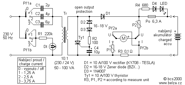
Leaving aside the complex chargers, "stuffed" electronics capacitor charger is one of the best connections. Charging current is limited by the resistor (or other element of the changing excess energy into heat), but the reactance of the capacitor to the...
W3HWJ Radio Receiver Projects
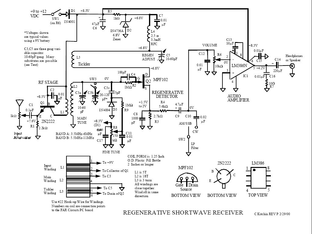
The logical first choice was to start with simple regenerative circuits, utilizing one or two transistors and possibly a basic audio amplifier with a single integrated circuit. A few simple tube radios purchased at flea markets will delay any tube...
High-pressure centralized compensation capacitor circuit
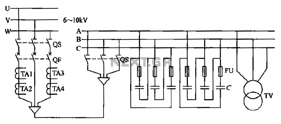
The compensation system is designed to focus on a high-pressure, high-voltage capacitor bank installed in the substation 6-10 kV bus. Compensation can only be implemented in this manner for the 6-10 kV bus before the reactive power on the line,...
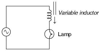
Variable inductor
Wind hundreds of turns of magnet wire around a paper tube. Connect this homemade inductor in series with an AC power supply and a lamp to create a circuit. When the tube is empty, the lamp should shine brightly. When...
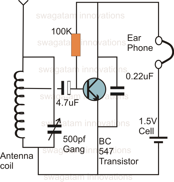
make this one transistor radio receiver
This is likely the simplest radio that can be assembled. The circuit design is straightforward enough to be completed in just a few minutes, allowing users to listen to their favorite programs immediately. The circuit of a single transistor radio,...
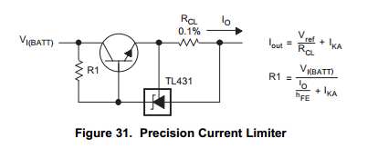
Capacitor Charging Circuit
This Korean SuperCap OEM supports usage in series configurations. Consider whether the implementation will be manual or automatic, such as with a smart battery charger or a power fail backup circuit. It is essential to balance the voltage and provide...
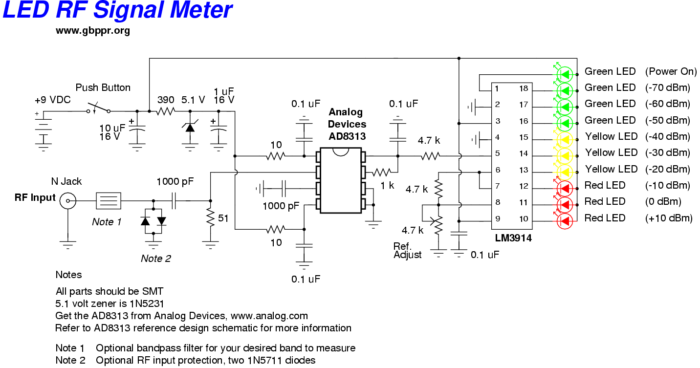
led rf signal meter
This RF Wave Absorption meter detects signals from 10 centimeters to 10 meters, depending on the setting of the 22 MegOhm gain adjustment potentiometer and the transmitter power. The RF signal is captured through germanium OA91 diodes and rectified to...
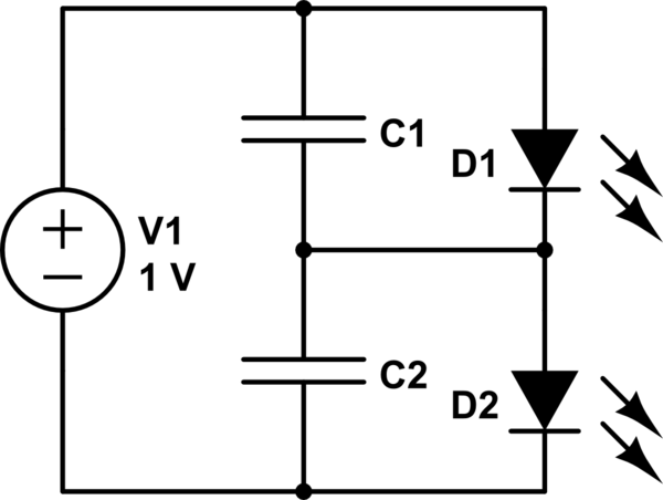
Charging a low-voltage high-C capacitor. Efficiently
The first option is a Zener diode. There are several 2.2V Zener diodes available that could adequately protect the capacitor. However, a significant drawback is that half the energy may be wasted across the diode short. The question arises whether...
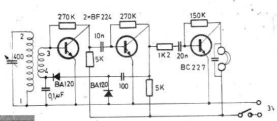
Radio receiver circuit for long and medium wave
Oscillating circuits (coils) are constructed on a ferrite bar. For long wave reception, winding "1-2" consists of 135 turns, while winding "3-4" consists of 20 turns. For medium wave reception, winding "1-2" has 75 turns, and winding "3-4" has 7...