


Hf Broadband Antenna Preamp Circuit
#HF
#broadband
#antenna
#preamplifier
#toroidal transformer
#LC network
#resistive attenuators
#MAR-x device
#pi-network
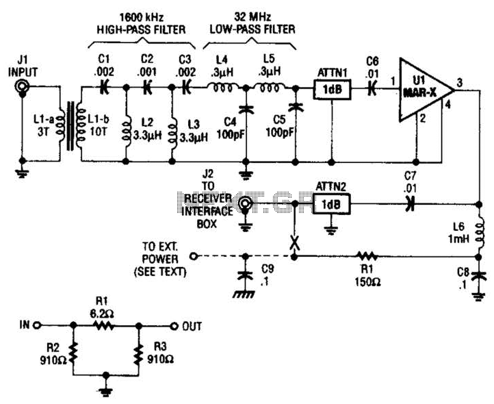
Description: The HF/SW receiver preamplifier consists of a broadband toroidal transformer (LI-a and Ll-b), an LC network featuring a 1600-kHz high-pass filter and a 32-MHz low-pass filter, inductors L2 and L3 (26 turns of #26 enameled wire wound on an Amidon Associates T-50-2 red toroidal core), a pair of resistive attenuators (ATTN1 and ATTN2), and a MAR-x device. This configuration illustrates the structure of a basic 1-dB pi-network resistor attenuator. Additionally, this method describes how to supply DC power to a preamplifier using only the RF coaxial cable.
The HF/SW receiver preamplifier is designed to enhance the signal reception capabilities of high-frequency shortwave radio systems. The use of a broadband toroidal transformer allows for efficient impedance matching and broad frequency response, which is crucial for capturing a wide range of signals. The transformer components, LI-a and Ll-b, are integral in ensuring minimal signal loss and maintaining fidelity across the desired frequency spectrum.
The LC network plays a vital role in filtering out unwanted frequencies, with the high-pass filter set at 1600 kHz effectively blocking lower-frequency noise, while the low-pass filter at 32 MHz ensures that higher-frequency signals beyond this threshold are attenuated. This dual filtering mechanism helps to optimize the quality of the received signals, allowing for clearer audio output and improved overall performance of the receiver.
Inductors L2 and L3, constructed with 26 turns of #26 enameled wire on an Amidon Associates T-50-2 toroidal core, are configured to enhance the inductance and contribute to the stability of the circuit. The choice of a toroidal core minimizes electromagnetic interference and enhances the efficiency of the inductors.
The resistive attenuators, ATTN1 and ATTN2, are designed as a pi-network configuration, which effectively reduces the signal amplitude without introducing significant distortion. This is particularly useful in preventing overload of subsequent stages in the receiver, ensuring that the signal remains within optimal levels for processing.
The MAR-x device included in the design serves as a low-noise amplifier, which is crucial for boosting weak signals received by the antenna, thus improving the overall sensitivity of the receiver.
Furthermore, the method of supplying DC power through the RF coaxial cable is noteworthy as it simplifies the overall system design by eliminating the need for separate power lines. This approach allows for a cleaner installation and reduces the potential for interference from external power sources. This technique is particularly advantageous in portable or compact receiver designs where space and simplicity are paramount.
Overall, the combination of these components creates a robust preamplification stage that significantly enhances the performance of HF/SW receivers, enabling better reception of weak signals and improving the listening experience. The HF/SW receiver preamplifier is comprised of a broadband toroidal transformer (LI-a and Ll-b), LC network (comprised of a 1600-kHz, high- pass filter-and a 32-MHz, low-pass filter), L2 and L3 (26 turns of #26 enameled wire wound on an Amidon Associates T-50-2, red, toroidal core), a pair of resistive attenuators (ATTN1 and ATTN2), and a MAR-x device.Shown here is the composition of a basic 1-dB pi-network resistor antenuator. This is the method of supplying dc power to a preamplifier using only the RF coax cable.
The HF/SW receiver preamplifier is designed to enhance the signal reception capabilities of high-frequency shortwave radio systems. The use of a broadband toroidal transformer allows for efficient impedance matching and broad frequency response, which is crucial for capturing a wide range of signals. The transformer components, LI-a and Ll-b, are integral in ensuring minimal signal loss and maintaining fidelity across the desired frequency spectrum.
The LC network plays a vital role in filtering out unwanted frequencies, with the high-pass filter set at 1600 kHz effectively blocking lower-frequency noise, while the low-pass filter at 32 MHz ensures that higher-frequency signals beyond this threshold are attenuated. This dual filtering mechanism helps to optimize the quality of the received signals, allowing for clearer audio output and improved overall performance of the receiver.
Inductors L2 and L3, constructed with 26 turns of #26 enameled wire on an Amidon Associates T-50-2 toroidal core, are configured to enhance the inductance and contribute to the stability of the circuit. The choice of a toroidal core minimizes electromagnetic interference and enhances the efficiency of the inductors.
The resistive attenuators, ATTN1 and ATTN2, are designed as a pi-network configuration, which effectively reduces the signal amplitude without introducing significant distortion. This is particularly useful in preventing overload of subsequent stages in the receiver, ensuring that the signal remains within optimal levels for processing.
The MAR-x device included in the design serves as a low-noise amplifier, which is crucial for boosting weak signals received by the antenna, thus improving the overall sensitivity of the receiver.
Furthermore, the method of supplying DC power through the RF coaxial cable is noteworthy as it simplifies the overall system design by eliminating the need for separate power lines. This approach allows for a cleaner installation and reduces the potential for interference from external power sources. This technique is particularly advantageous in portable or compact receiver designs where space and simplicity are paramount.
Overall, the combination of these components creates a robust preamplification stage that significantly enhances the performance of HF/SW receivers, enabling better reception of weak signals and improving the listening experience. The HF/SW receiver preamplifier is comprised of a broadband toroidal transformer (LI-a and Ll-b), LC network (comprised of a 1600-kHz, high- pass filter-and a 32-MHz, low-pass filter), L2 and L3 (26 turns of #26 enameled wire wound on an Amidon Associates T-50-2, red, toroidal core), a pair of resistive attenuators (ATTN1 and ATTN2), and a MAR-x device.Shown here is the composition of a basic 1-dB pi-network resistor antenuator. This is the method of supplying dc power to a preamplifier using only the RF coax cable.
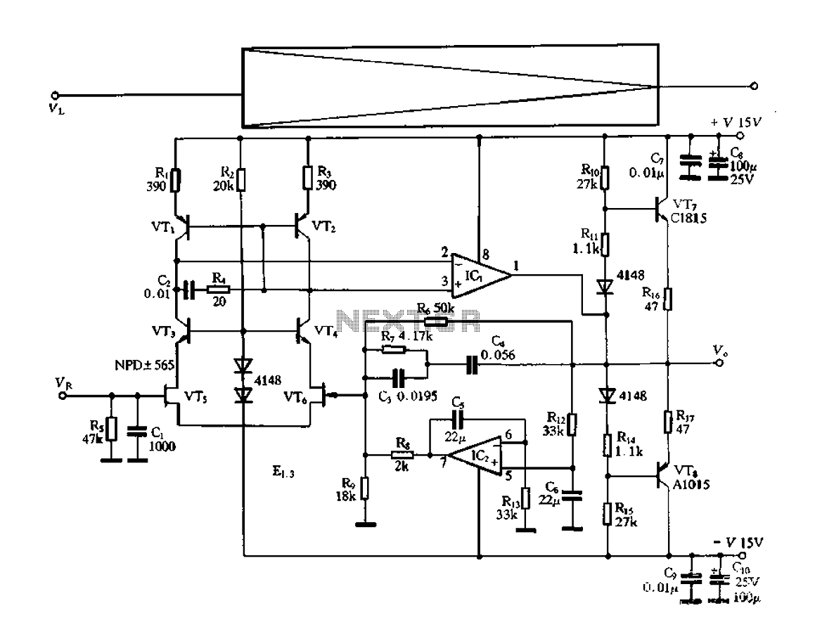
Electronic switching preamplifier
The electronic switch functions as a multifunctional preamplifier. It features a five-way touch electronic switch, a high-speed DC servo RIAA ultralow distortion amplifier, and can control volume, tone, and power amplifier electrical path phase. The TC9152, shown in Figure 3-24,...
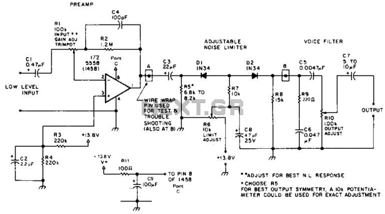
Receiver Af Noise Limiter For Low-Level Signals Circuit
A preamplifier in the audio frequency range amplifies a noisy audio signal to drive a diode clipper. Suitable audio input levels would be in the 10-mV to 1-V range.
The audio preamplifier circuit is designed to enhance weak audio signals, typically...
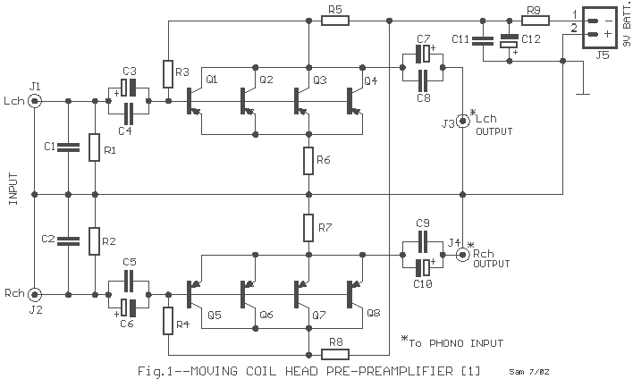
Moving Coil Head Pre-preamplifier
The description pertains to a specific type of preamplifiers that are designed to amplify the low output of Moving coil heads, enabling their drive to an input PHONO [RIAA] of a preamplifier. Moving coil heads present certain challenges that require...
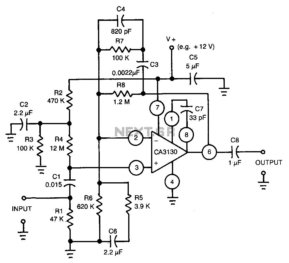
Equalized-preamp-for-magnetic-phonograph-cartridges
This circuit utilizes a CA3130 BiMOS operational amplifier. The amplifier is equalized to meet RIAA playback frequency response specifications. It serves as a preamplifier following a magnetic tape head.
The circuit employs the CA3130 BiMOS op-amp, which combines the benefits of...
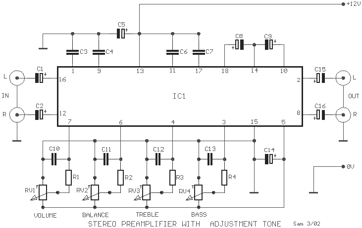
Stereo Preamplifier with adjustment tone circuit
A simple preamplifier circuit is often required, utilizing a few components for ease of construction. This circuit employs an operational amplifier, specifically the Motorola TCA5550, which features a dual amplifier configuration. It provides outputs for adjusting volume, balance, treble, and...

The ATL-3 Loop Antenna
All ATL-3 loop windings are center-tapped and balanced with respect to their amplifier/receiver chassis ground, which leads to self-cancellation of electric field interference. Magnetic noise fields, such as those from televisions and electric meter boxes, or electromagnetically radiated interferences, can...
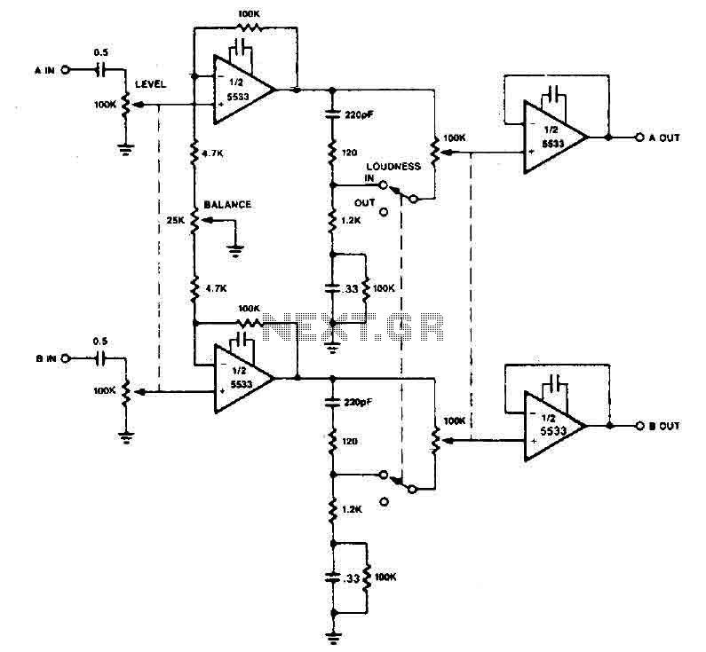
Stereo Preamplifier with balance and loudness
The preamplifier circuit utilizes the 5533 chip and incorporates a combination of balance and volume controls. Given the nonlinearity of the human auditory system, low frequencies are required to be amplified at lower listening levels. Additionally, level and LOUDNESS controls...
Four Foot Box Loop Antenna
Please find attached your copy of my four foot unamplified box loop. It will tune from 525 kHz to about 1710 kHz covering the entire Broadcast Band. The umbrella stand described in the article is the type you would use...
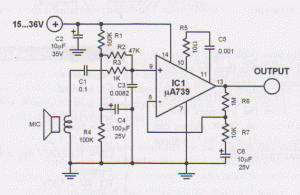
Dynamic mic preamplifier circuit
This microphone preamplifier utilizes the low-noise integrated circuit (IC) uA739. The circuit serves as an example of an effective design for preamplifying dynamic microphones. The IC contains two operational amplifiers.
The uA739 is a precision integrated circuit known for its low...