


High-Pass Filter controls UHF Ingress to Satellite DBS Tuner
#UHF
#filter
#satellite
#DBS tuner
#stopband attenuation
#insertion loss
#RF design
#signal processing
#high-pass filter
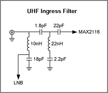
Description: This application note discusses the design of a UHF ingress filter intended for a Satellite DBS tuner. The filter is designed to achieve 20 dB of stopband attenuation within the frequency range of 54-650 MHz, while maintaining an in-band insertion loss of 0.7 dB.
The UHF ingress filter is a crucial component in satellite communication systems, specifically for Direct Broadcast Satellite (DBS) tuners. Its primary function is to eliminate unwanted signals and noise from the UHF band, ensuring that the desired satellite signals are received with minimal interference. The filter operates effectively within the specified frequency range of 54-650 MHz, which encompasses various potential sources of ingress noise.
The design of the filter typically involves a combination of passive components such as inductors and capacitors, arranged to create a low-pass or band-stop filter configuration. The choice of components and their respective values is critical to achieving the desired attenuation characteristics. In this case, the filter is engineered to provide 20 dB of attenuation in the stopband, significantly reducing the impact of out-of-band signals on the performance of the DBS tuner.
In-band insertion loss is another important parameter that influences the overall performance of the filter. With a measured insertion loss of 0.7 dB within the passband, the filter allows the desired satellite signals to pass through with minimal signal degradation. This low insertion loss is essential for maintaining signal integrity and ensuring high-quality reception of satellite broadcasts.
To validate the filter's performance, simulation tools may be employed to model the frequency response and to optimize the component values. Additionally, practical testing should be conducted to measure the actual insertion loss and stopband attenuation, verifying that the filter meets the design specifications.
Overall, the UHF ingress filter is a vital element in the design of Satellite DBS tuners, contributing to the reliability and quality of satellite communication by effectively mitigating unwanted interference in the specified frequency range.This application note covers the design of a UHF ingress filter for a Satellite DBS tuner. The filter provides 20dB of stopband attenuation from 54-650MHz with 0.7dB in-band insertion loss..
The UHF ingress filter is a crucial component in satellite communication systems, specifically for Direct Broadcast Satellite (DBS) tuners. Its primary function is to eliminate unwanted signals and noise from the UHF band, ensuring that the desired satellite signals are received with minimal interference. The filter operates effectively within the specified frequency range of 54-650 MHz, which encompasses various potential sources of ingress noise.
The design of the filter typically involves a combination of passive components such as inductors and capacitors, arranged to create a low-pass or band-stop filter configuration. The choice of components and their respective values is critical to achieving the desired attenuation characteristics. In this case, the filter is engineered to provide 20 dB of attenuation in the stopband, significantly reducing the impact of out-of-band signals on the performance of the DBS tuner.
In-band insertion loss is another important parameter that influences the overall performance of the filter. With a measured insertion loss of 0.7 dB within the passband, the filter allows the desired satellite signals to pass through with minimal signal degradation. This low insertion loss is essential for maintaining signal integrity and ensuring high-quality reception of satellite broadcasts.
To validate the filter's performance, simulation tools may be employed to model the frequency response and to optimize the component values. Additionally, practical testing should be conducted to measure the actual insertion loss and stopband attenuation, verifying that the filter meets the design specifications.
Overall, the UHF ingress filter is a vital element in the design of Satellite DBS tuners, contributing to the reliability and quality of satellite communication by effectively mitigating unwanted interference in the specified frequency range.This application note covers the design of a UHF ingress filter for a Satellite DBS tuner. The filter provides 20dB of stopband attenuation from 54-650MHz with 0.7dB in-band insertion loss..
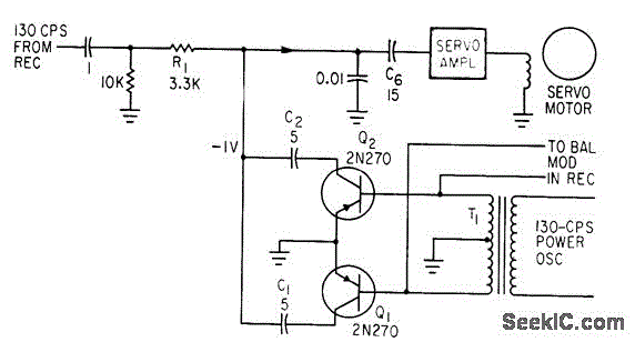
SYNCHRONOUS FILTER FOR ADF
Separates 130-cps motor drive voltage from voice frequencies in the output of an ADF receiver. P. V. Sparks, Servo Filter and Gain Control Improve Automatic Direction Finder, Electronics, 34:23, p 110-113.
The circuit described functions as a filter that effectively separates...
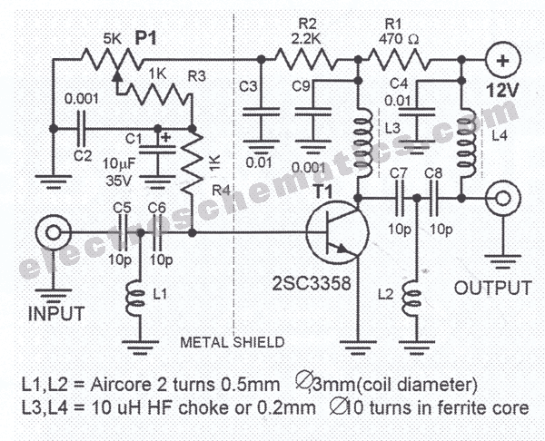
UHF Antenna Amplifier Circuit
This amplifier circuit is designed to enhance TV signals in the UHF range. It employs a low-noise transistor, providing an amplification of 10 to 15 dB within the frequency spectrum of 400 MHz to 850 MHz. It is crucial to...
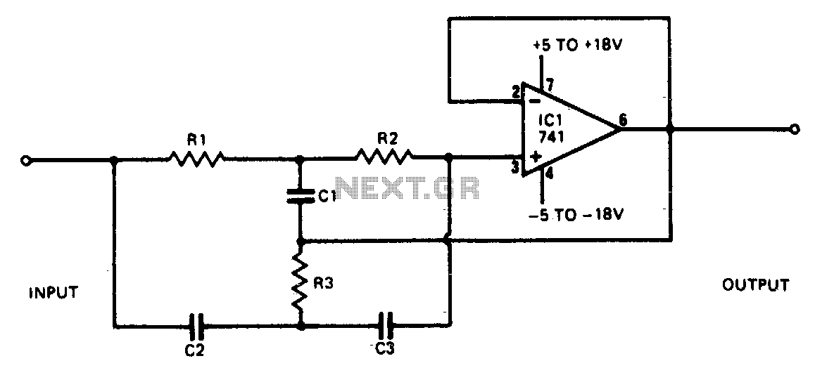
Rejection filter
This narrowband filter utilizing the 741 operational amplifier can achieve a rejection level of up to 60 dB. By employing resistors with a value of 100 K ohms and capacitors of 320 pF, the circuit effectively rejects frequencies at 50...
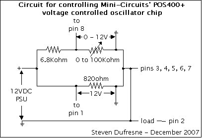
oscillator mcpos400 plus
This is a UHF oscillator circuit designed to utilize the Mini-Circuits POS-400+ voltage-controlled oscillator chip. By applying a voltage between 0 to 12V on pin 8, it produces a sine wave output ranging from 200MHz to 380MHz on pin 2;...
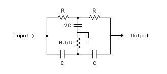
Twin-T RC Notch Filter
The two T-notch filter can be utilized to block unwanted frequencies or, when incorporated into an operational amplifier, function as a bandpass filter. The notch frequency occurs when the capacitive reactance equals the resistance (Xc = R), and if these...
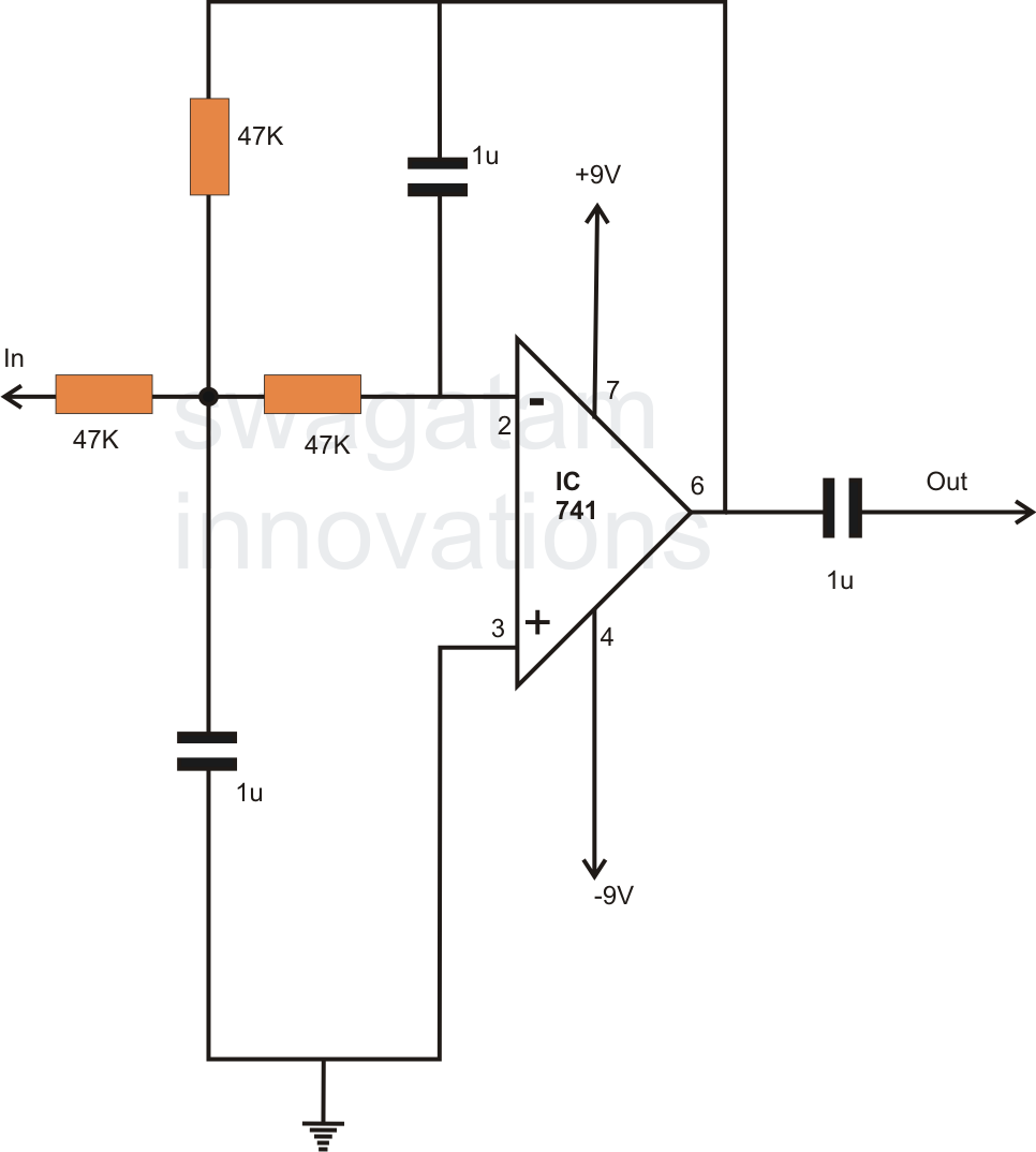
how to make simple active low pass
In electronics, filter circuits are primarily used to restrict the passage of certain frequency ranges while allowing other frequency bands to proceed to subsequent stages of the circuit. A high-pass filter circuit permits only frequencies that exceed a specified range,...
SYNCHRONOUS FILTER FOR ADF
Separates 130-cps motor drive voltage from voice frequencies in the output of an ADF receiver. P. V. Sparks, Servo Filter and Gain Control Improve Automatic Direction Finder, Electronics, 34:23, p 110-113.
The circuit described functions as a filter that effectively separates...
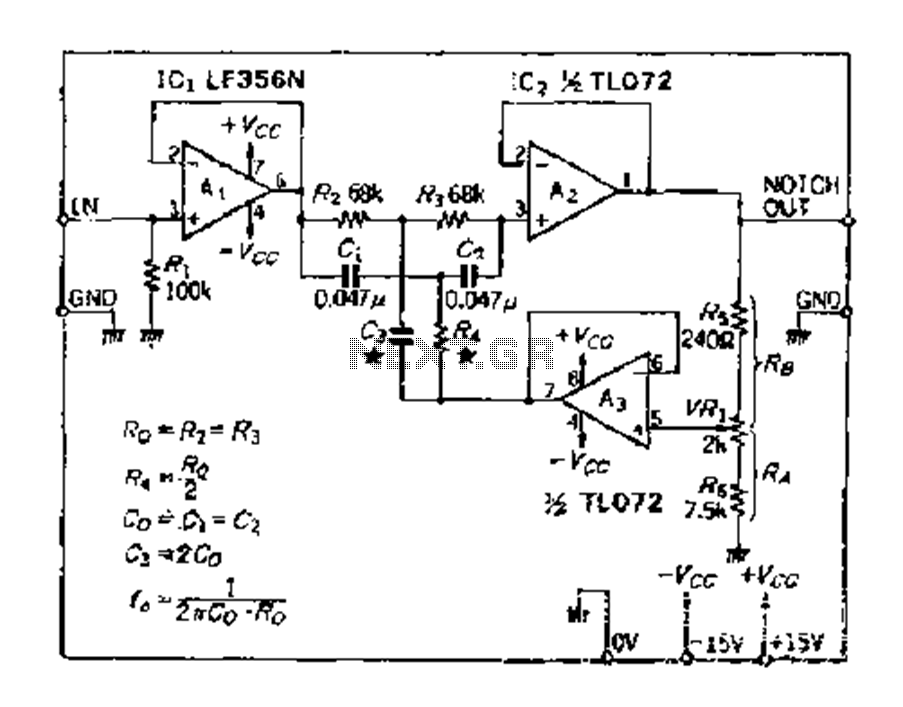
The Q value of the variable notch filter
The double R circuit consists of three resistors and three capacitors, exhibiting substantially symmetrical double passive attenuation characteristics of the filter element with a frequency response range of 0 to 0.2. The parameters are determined as follows: Rz, R3, CL,...
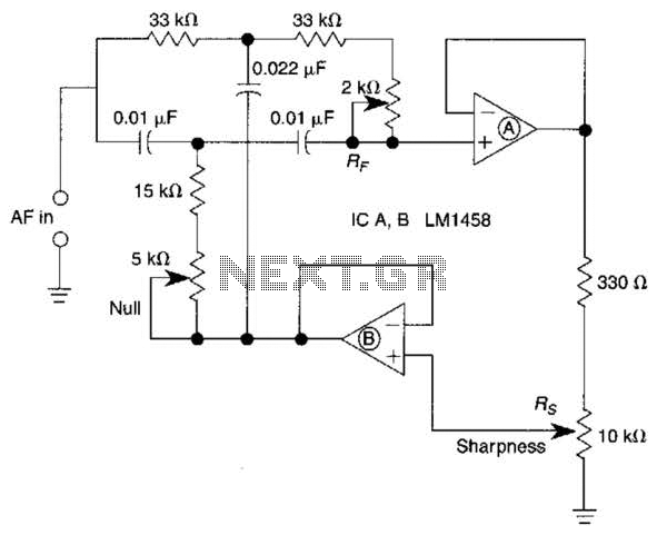
Variable Q Filter For 400Hz Circuit
A bootstrapped twin notch filter in this circuit can yield an effective Q of up to 10. Rs adjusts the feedback, hence the Q. Values of C1 and C2 can be changed to alter the frequency. RF is a fine-tune...