


K7LR Memorial Receiver
Description: This web page is a memorial to Mike Caughran, KL7R, who passed away unexpectedly in January 2007. Mike was an enthusiastic experimenter, well-regarded in the homebrew radio electronics community. He is best known as the co-creator and collaborator with Bill Meara, M0HBR, on the podcast Solder Smoke. A dedicated science and technology enthusiast, Mike had an impressive understanding of general science and a keen interest in minimalist RF designs. He was known for his work on 40 and 80-meter CW, as well as voice communication on eQSO. Mike was the first to refer to this website as the "popcorn site." His interest in digital circuits is honored through a series of receiver experiments presented here. Mike Caughran is remembered as a remarkable, kind, and passionate homebuilder. Special acknowledgment is given to Wes, W7ZOI, for his guidance and suggestions that improved many circuits on this site, which heavily draws from designs presented in EMRFD. The KL7R memorial receiver, depicted on this page, is the culmination of extensive experimentation. Most circuit ideas originated from EMRFD. Mike consistently challenged himself through experimentation, testing, and expanding his knowledge. The joy of discovery fueled his passion. Inspired by his spirit of inquiry, efforts were made to construct a receiver incorporating at least one digital circuit. Many days yielded no results, and progress was often minimal, reflecting the challenging periods all experimenters face. Design and circuit failures can be discouraging, leading to wasted components. However, persistence led to gradual successes and increased confidence. The outcome was enhanced knowledge and a unique, popcorn direct conversion receiver, intended to inspire further experimentation. Figure 1 illustrates the front-end band-pass filter. Alternatives, such as a different 7 MHz band-pass filter circuit, are suggested if a 3.3 pF coupling capacitor is unavailable. Additional information regarding parts used on this site can be found on the Webmaster's page. A photograph of the Figure 1 breadboard reveals that inductors were arranged at right angles to minimize unwanted coupling. The copper-clad L-C tank divider is optional, and the 51-ohm load resistor on the right was removed after testing. Figure 2 depicts the BJT driver, D flip-flop, and CMOS switch product detector. The 14 MHz VFO connects to Q1 through a 0.1 µF coupling capacitor shown on the VFO schematic. A dual FET bus switch (CBT3306) functions as the product detector, with an on-resistance of approximately 3 ohms. For those seeking a challenge, a 14-pin SOIC switch like the QUAD FET SN74CBT3125DR can be employed, with two pairs of the four switches connected in parallel. Three different CMOS switches were tested in the U2 slot, including the MAX4066CPD and the 74HC4053, configured according to their datasheets. The performance of these two switches was underwhelming when compared to a 7 dBm diode ring mixer. Numerous experiments were conducted, including operating the 4066 at a 12-volt VCC to reduce on-resistance, necessitating modifications to much of Figure 2. Integrating 5-volt and 12-volt logic ICs posed challenges. These experiments consumed a significant amount of time. Ultimately, it was concluded that if a CMOS switch is to be used, selecting a component with low on-resistance is advisable. Consequently, the use of DIP IC CMOS switches (4053, 4052, 4066, etc.) as mixers and product detectors has been discontinued, although they may still be suitable in other contexts. The CBT3306 has proven to be an excellent choice, comparable to a diode ring mixer.
The KL7R memorial receiver circuit is designed to provide a unique exploration of digital and analog integration in RF applications. The front-end band-pass filter is critical for isolating the desired frequency range, ensuring minimal interference from adjacent channels. The design allows for adaptability, accommodating various components based on availability, which is essential for hobbyists and experimenters. The use of a BJT driver and a D flip-flop in the signal processing chain enhances the receiver's performance, enabling reliable detection of signals.
The choice of the CBT3306 switch reflects a strategic decision to prioritize low on-resistance and high performance, which is crucial for maintaining signal integrity in RF applications. The inclusion of a variable frequency oscillator (VFO) allows for tuning across the desired frequency range, with careful attention to coupling methods to minimize signal loss. The experimentation process outlined in this project highlights the iterative nature of circuit design, where each failure contributes to a deeper understanding of RF principles and circuit behavior.
Overall, this memorial project serves not only as a tribute to Mike Caughran but also as a valuable resource for those interested in homebrew radio electronics. The documentation of design choices, challenges faced, and solutions implemented provides insights into the experimental process, encouraging others to engage in their own explorations within the field of electronics.This web page is a memorial to Mike Caughran, KL7R, who died suddenly in January 2007. Mike was a passionate experimenter who was embraced by the homebrew radio electronics community. He was best known as the co-creator of and sidekick to Bill Meara, M0HBR on the podcast Solder Smoke. Mike was a hardcore science and technology buff. His knowledge of general science and curiosity about minimalist RF designs was amazing. I worked Mike on 40 and 80 meter CW and later by voice on eQSO. Mike was the first person to refer to this web site as the "popcorn site". He held an interest in digital circuits. In tribute to Mike, a series of receiver experiments which includes some digital circuits are presented. Mike Caughran will be remembered as a remarkable, kind and passionate homebuilder. My special thanks to Wes, W7ZOI for his coaching and suggestions to improve many of the circuits on this web page.
This web page borrows heavily from his designs as presented in EMRFD. Shown above is the receiver block diagram. The KL7R memorial receiver depicted on this web page is the final output of many hours of experimentation. Most of the circuits or circuit ideas originated in EMRFD. From our conversations, Mike was always challenging himself; experimenting, testing and pushing his knowledge threshold.
The joy of discovery motivated him. Fired by his spirit of inquiry, I explored methods to build a receiver containing at least 1 digital circuit. On many days, I accomplished nothing. The circuits did not work and little to no progress was made. These were the difficult dry spells all experimenters must endure. Design and circuit failures can be very disheartening. I also wasted a lot of parts. However, I kept going and slowly successes occurred and my confidence rose. The end result was a little more knowledge and a cool, popcorn, direct conversion receiver which I hope will provide ideas and inspiration for your own experiments.
Figure 1 shows the front end band-pass filter. If you can`t obtain a 3. 3 pF coupling capacitor, try this other 7 MHz band-pass filter circuit or perhaps just design your own. See the Webmaster`s page for information concerning many of the parts used on this web page. Shown above is a photograph of the Figure 1 breadboard. The inductors were spaced apart at right angles to reduce unwanted coupling. The copper clad board L-C tank divider is not necessary. The 51 ohm load resistor seen to the right was removed after testing. Shown above in Figure 2 is the BJT driver, D flip-flop and the CMOS switch product detector. The 14 MHz VFO connects to Q1 via a 0. 1 uF coupling capacitor that is shown on the VFO schematic. A dual FET bus switch ( CBT3306 ) serves as the product detector. The on-resistance of this switch is only around 3 ohms! If you are ambitious, you might try using a 14 pin SOIC switch such as the QUAD FET SN74CBT3125DR with 2 pairs of the 4 switches wired in parallel.
I tried 3 different CMOS switches in the U2 slot. The other switches were the MAX4066CPD and a 74HC4053 (wired up appropriately using their datasheets). The insertion loss and performance of these 2 switches was disappointing. My bench standard for comparison was a 7 dBm diode ring mixer. Numerous experiments were performed. For example, I tried running the 4066 at 12 volts VCC to minimize its on-resistance and had to modify most of Figure 2 as well.
Being new to digital, blending 5 volt and 12 volt logic IC required great effort to get it working properly. These experiments consumed the better part of 2 days. My conclusion was that if you are going to go to the trouble of make a CMOS switch work, you might as well use a part that has a low on-resistance.
Hence, I have since abandoned using DIP IC CMOS switches (4053, 4052, 4066 etc. ) as mixers and product detectors. They may still be a good choice in your own context. The CBT3306 is outstanding and very similar to the diode ring mixe
The KL7R memorial receiver circuit is designed to provide a unique exploration of digital and analog integration in RF applications. The front-end band-pass filter is critical for isolating the desired frequency range, ensuring minimal interference from adjacent channels. The design allows for adaptability, accommodating various components based on availability, which is essential for hobbyists and experimenters. The use of a BJT driver and a D flip-flop in the signal processing chain enhances the receiver's performance, enabling reliable detection of signals.
The choice of the CBT3306 switch reflects a strategic decision to prioritize low on-resistance and high performance, which is crucial for maintaining signal integrity in RF applications. The inclusion of a variable frequency oscillator (VFO) allows for tuning across the desired frequency range, with careful attention to coupling methods to minimize signal loss. The experimentation process outlined in this project highlights the iterative nature of circuit design, where each failure contributes to a deeper understanding of RF principles and circuit behavior.
Overall, this memorial project serves not only as a tribute to Mike Caughran but also as a valuable resource for those interested in homebrew radio electronics. The documentation of design choices, challenges faced, and solutions implemented provides insights into the experimental process, encouraging others to engage in their own explorations within the field of electronics.This web page is a memorial to Mike Caughran, KL7R, who died suddenly in January 2007. Mike was a passionate experimenter who was embraced by the homebrew radio electronics community. He was best known as the co-creator of and sidekick to Bill Meara, M0HBR on the podcast Solder Smoke. Mike was a hardcore science and technology buff. His knowledge of general science and curiosity about minimalist RF designs was amazing. I worked Mike on 40 and 80 meter CW and later by voice on eQSO. Mike was the first person to refer to this web site as the "popcorn site". He held an interest in digital circuits. In tribute to Mike, a series of receiver experiments which includes some digital circuits are presented. Mike Caughran will be remembered as a remarkable, kind and passionate homebuilder. My special thanks to Wes, W7ZOI for his coaching and suggestions to improve many of the circuits on this web page.
This web page borrows heavily from his designs as presented in EMRFD. Shown above is the receiver block diagram. The KL7R memorial receiver depicted on this web page is the final output of many hours of experimentation. Most of the circuits or circuit ideas originated in EMRFD. From our conversations, Mike was always challenging himself; experimenting, testing and pushing his knowledge threshold.
The joy of discovery motivated him. Fired by his spirit of inquiry, I explored methods to build a receiver containing at least 1 digital circuit. On many days, I accomplished nothing. The circuits did not work and little to no progress was made. These were the difficult dry spells all experimenters must endure. Design and circuit failures can be very disheartening. I also wasted a lot of parts. However, I kept going and slowly successes occurred and my confidence rose. The end result was a little more knowledge and a cool, popcorn, direct conversion receiver which I hope will provide ideas and inspiration for your own experiments.
Figure 1 shows the front end band-pass filter. If you can`t obtain a 3. 3 pF coupling capacitor, try this other 7 MHz band-pass filter circuit or perhaps just design your own. See the Webmaster`s page for information concerning many of the parts used on this web page. Shown above is a photograph of the Figure 1 breadboard. The inductors were spaced apart at right angles to reduce unwanted coupling. The copper clad board L-C tank divider is not necessary. The 51 ohm load resistor seen to the right was removed after testing. Shown above in Figure 2 is the BJT driver, D flip-flop and the CMOS switch product detector. The 14 MHz VFO connects to Q1 via a 0. 1 uF coupling capacitor that is shown on the VFO schematic. A dual FET bus switch ( CBT3306 ) serves as the product detector. The on-resistance of this switch is only around 3 ohms! If you are ambitious, you might try using a 14 pin SOIC switch such as the QUAD FET SN74CBT3125DR with 2 pairs of the 4 switches wired in parallel.
I tried 3 different CMOS switches in the U2 slot. The other switches were the MAX4066CPD and a 74HC4053 (wired up appropriately using their datasheets). The insertion loss and performance of these 2 switches was disappointing. My bench standard for comparison was a 7 dBm diode ring mixer. Numerous experiments were performed. For example, I tried running the 4066 at 12 volts VCC to minimize its on-resistance and had to modify most of Figure 2 as well.
Being new to digital, blending 5 volt and 12 volt logic IC required great effort to get it working properly. These experiments consumed the better part of 2 days. My conclusion was that if you are going to go to the trouble of make a CMOS switch work, you might as well use a part that has a low on-resistance.
Hence, I have since abandoned using DIP IC CMOS switches (4053, 4052, 4066 etc. ) as mixers and product detectors. They may still be a good choice in your own context. The CBT3306 is outstanding and very similar to the diode ring mixe
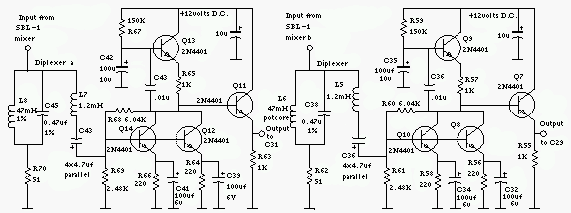
The R2 Single Sideband Direct Conversion Receiver
The old common-base audio preamp, which has a noise figure of 5 dB, is a clear candidate for improvement in noise performance. A common-emitter configuration with shunt feedback provides an input resistance of 50 ohms, which is preferred by the...
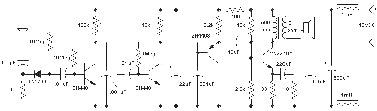
Amazing All-Band Receiver
The Amazing All-Band Receiver is essentially a diode detector followed by a high-gain audio amplifier. This device is not a multi-band receiver; it captures all signals simultaneously. The detector utilizes a biased Schottky diode for superior sensitivity and bandwidth, enabling...
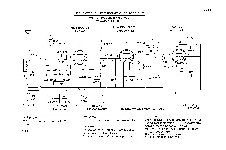
Battery Powered Tube Regenerative Receiver
The basic regenerative design is quite common. Before the schematic is created, there is a "concept stage," followed by the "available components stage," returning to the "concept stage," then moving on to the "mechanical/electrical layout stage," and finally sketching a...
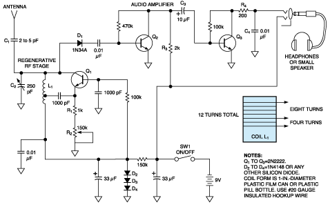
Simple receiver with microvolt sensitivity
The three-transistor circuit costs less than $10 to build, uses commonly available components, and consumes less than 10 mA from a single 9V battery. By winding coil L1 as shown, the circuit can receive signals in the 5 to 15...
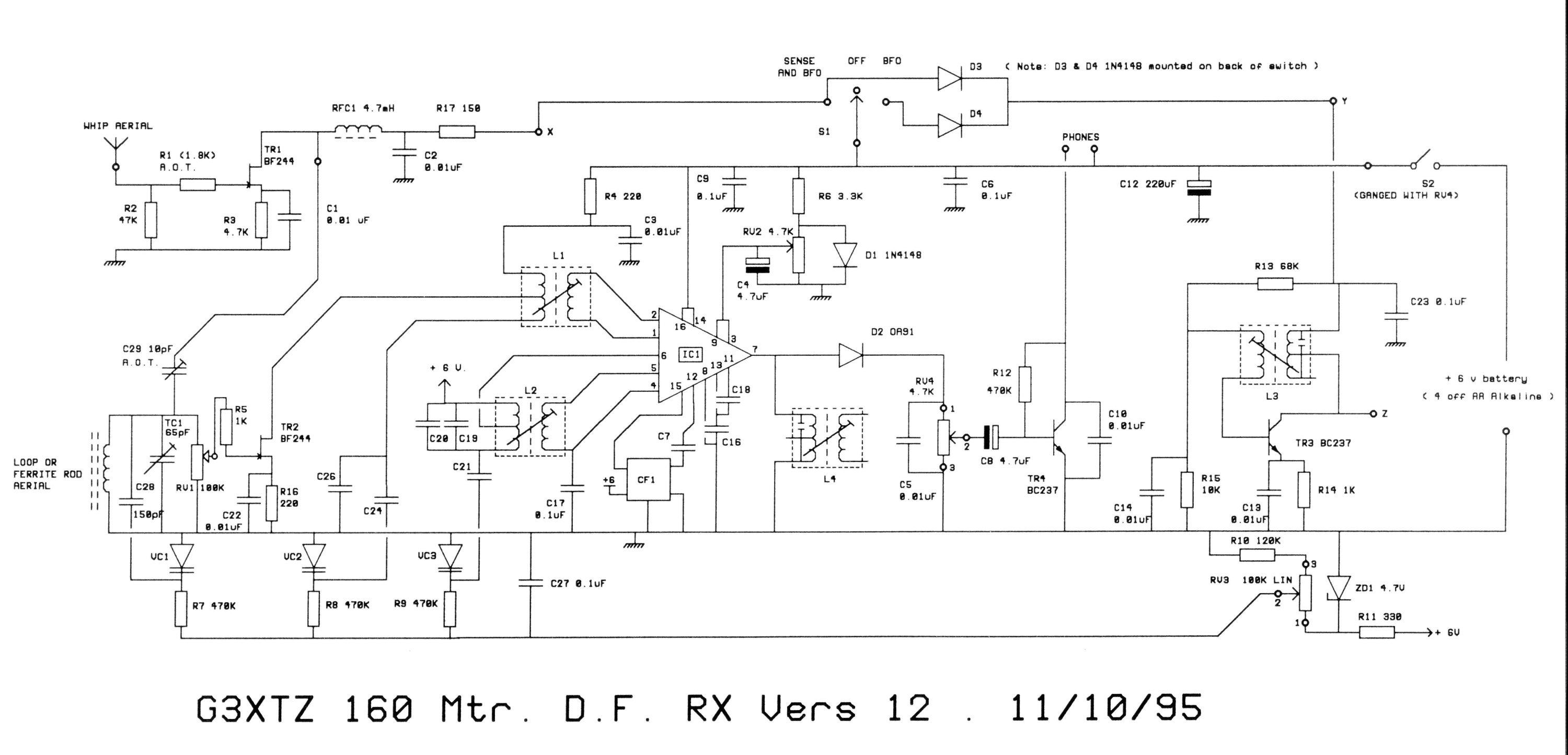
G3XTZ DF Rx Details
The receiver is constructed on a single-sided printed circuit board measuring 2 by 4.3 inches. Its compact size allows for installation in various enclosures, which should be adequately shielded. The main directional signal is captured by a tuned ferrite rod...
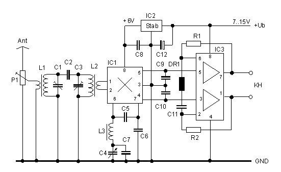
30m Band Receiver
The direct conversion receiver described consists of only a bandpass filter, mixer IC, VFO and audio filter. With only 22 parts, this simple circuit should take a few hours at the weekend to construct. For extra simplicity, eliminate L1 &...
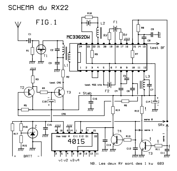
41-72MHz micro-receiver ( MC3362 )
This receiver weighs about 6 g, used in 41 and 72 MHz, met a great success with readers of the magazine. The RX22 is the subject of these lines is improved RX20. Adding a preamp-HF improving sensitivity. Establishment of an...
REGENERATIVE_SHORTWAVE_RECEIVER
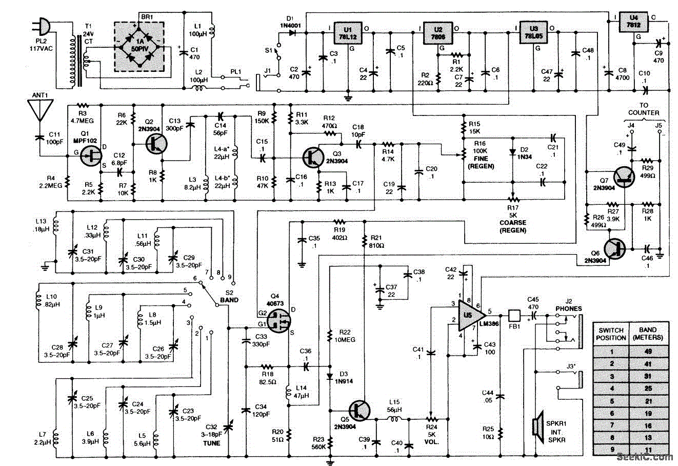
The receiver consists of multiple subassemblies, including an active antenna, an amplifier featuring regeneration control and band-switching circuitry, an AM detector, a power amplifier, and an output device such as an internal speaker, external speaker, or headphones. Additionally, it is...
Tuned Radio Frequency (TRF) Receiver
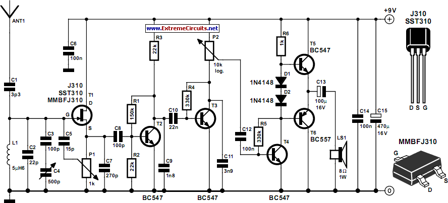
Superheterodyne receivers have been mass-produced since around 1924, but for reasons of cost did not become successful until the 1930s.
Superheterodyne receivers represent a pivotal advancement in radio technology, characterized by their ability to convert high-frequency signals into lower intermediate...