


LOW NOISE 420 MHz ATV RECEIVER CONVERTER
#RF amplifier
#mixer
#local oscillator
#IF amplifier
#420 MHz
#ATV
#signal conversion
#filter
#Q1
#M1
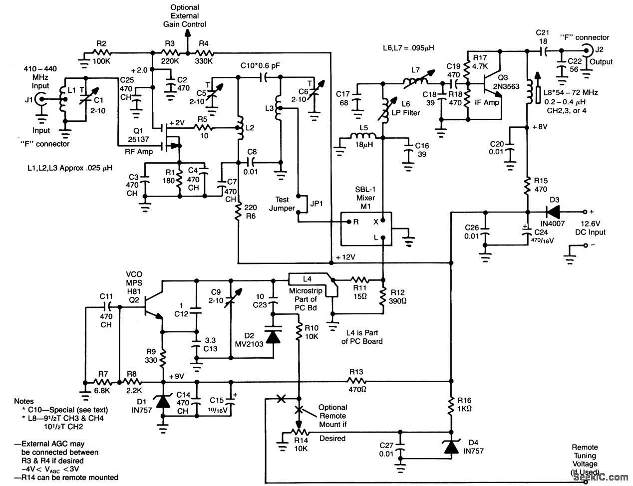
Description: L1, Q1, L2, and L3 form an RF amplifier stage that drives M1, a doubly balanced mixer. Q4 serves as a local oscillator stage operating in the 375-MHz range. Signals in the 420 to 450-MHz range from Q1 are mixed in M1 and subsequently passed through the filter formed by L6, L7, and C17, allowing only the 60 to 70-MHz signals (CH3 to CH4) to pass. The intermediate frequency (IF) signal is then sent to Q3, which acts as an IF amplifier. The overall gain is 25 dB, with a noise figure of less than 2 dB. A complete kit of all necessary components, including the printed circuit board, is available from North Country Radio, P.O. Box 53, Wykagyl Station, New Rochelle, NY 10804.
The circuit described consists of several key components that work together to process radio frequency signals. L1, Q1, L2, and L3 are integral to the RF amplification stage, where L1 and L2 typically serve as inductors that enhance the gain of the RF signals. Q1, likely a transistor or FET, amplifies the incoming RF signals before they are routed to the mixer.
M1, the doubly balanced mixer, is a critical component for combining the RF signal from Q1 with the local oscillator signal generated by Q4. The operation of the mixer allows for the downconversion of high-frequency signals to a lower intermediate frequency, which is more manageable for further processing. The local oscillator stage, Q4, is tuned to 375 MHz, ensuring that it can effectively mix with the incoming RF signals in the specified 420 to 450 MHz range.
The filtering stage, which includes L6, L7, and C17, is designed to selectively allow only the desired intermediate frequency signals (60 to 70 MHz) to pass through while attenuating unwanted frequencies. This is crucial for maintaining the integrity of the signal and minimizing interference from other frequencies.
The IF amplifier, Q3, boosts the filtered intermediate frequency signal, ensuring that it has sufficient power for subsequent stages in the signal processing chain. The overall performance of this circuit is impressive, achieving a gain of 25 dB and maintaining a low noise figure of less than 2 dB, which is essential for high-quality RF applications.
For those interested in building this circuit, a kit containing all necessary components, including the printed circuit board, is readily available from North Country Radio, providing an accessible option for enthusiasts and professionals alike.L1, Q1, L2, and L3 compose an RF amp’’fter stage that feeds Ml, a doubly balanced mixer. Q4 is alocal oscillator stage In the 375-MHz range Signals h the 420 ‰to 450-MHz range from Q1 are mixed in M1 and fed through filter L6/L7/C17, where only the 60- to 70-MHz (CH3 CH4) signals pass. The IF signal is passed to Q3, an IF amplifier. The overall gatrns 25 dB and the noise figure less than 2 dB. A kit of all parts, including the PC board, is available from North Country Radio, P. O. Box 53, Wykagyl Station, New Rochelle, NY 10804.
The circuit described consists of several key components that work together to process radio frequency signals. L1, Q1, L2, and L3 are integral to the RF amplification stage, where L1 and L2 typically serve as inductors that enhance the gain of the RF signals. Q1, likely a transistor or FET, amplifies the incoming RF signals before they are routed to the mixer.
M1, the doubly balanced mixer, is a critical component for combining the RF signal from Q1 with the local oscillator signal generated by Q4. The operation of the mixer allows for the downconversion of high-frequency signals to a lower intermediate frequency, which is more manageable for further processing. The local oscillator stage, Q4, is tuned to 375 MHz, ensuring that it can effectively mix with the incoming RF signals in the specified 420 to 450 MHz range.
The filtering stage, which includes L6, L7, and C17, is designed to selectively allow only the desired intermediate frequency signals (60 to 70 MHz) to pass through while attenuating unwanted frequencies. This is crucial for maintaining the integrity of the signal and minimizing interference from other frequencies.
The IF amplifier, Q3, boosts the filtered intermediate frequency signal, ensuring that it has sufficient power for subsequent stages in the signal processing chain. The overall performance of this circuit is impressive, achieving a gain of 25 dB and maintaining a low noise figure of less than 2 dB, which is essential for high-quality RF applications.
For those interested in building this circuit, a kit containing all necessary components, including the printed circuit board, is readily available from North Country Radio, providing an accessible option for enthusiasts and professionals alike.L1, Q1, L2, and L3 compose an RF amp’’fter stage that feeds Ml, a doubly balanced mixer. Q4 is alocal oscillator stage In the 375-MHz range Signals h the 420 ‰to 450-MHz range from Q1 are mixed in M1 and fed through filter L6/L7/C17, where only the 60- to 70-MHz (CH3 CH4) signals pass. The IF signal is passed to Q3, an IF amplifier. The overall gatrns 25 dB and the noise figure less than 2 dB. A kit of all parts, including the PC board, is available from North Country Radio, P. O. Box 53, Wykagyl Station, New Rochelle, NY 10804.
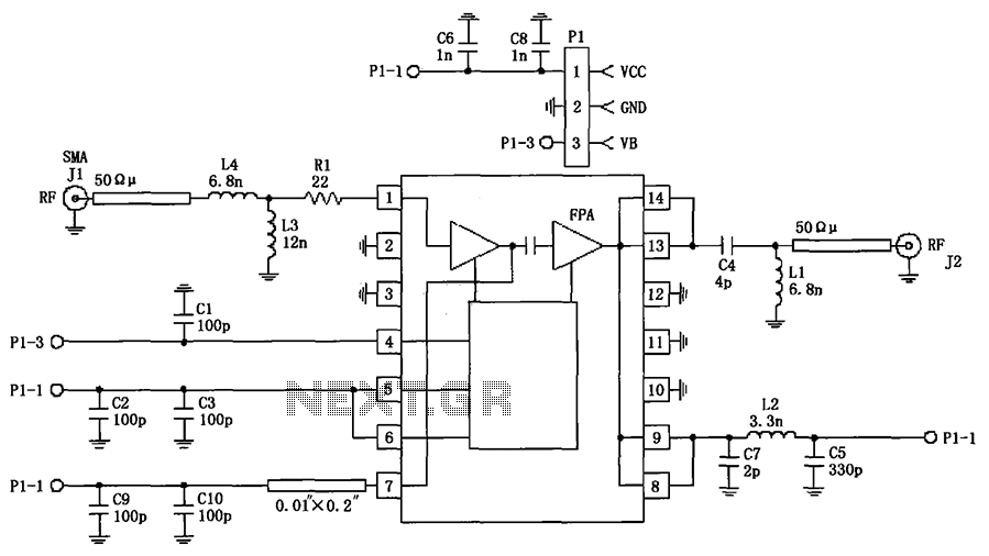
RF2103P schematic configuration of 915MHz RF amplifier
The circuit illustrated in FIG consists of the RF2103P 915MHz RF amplifier circuit. P1 serves as the outlet, where P1-1 connects to power Vcc, P1-2 connects to ground, and P1-3 is used for the power down control voltage VB. J1...
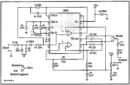
Speech Filter
A simple circuit that can switch between a sharp cutoff frequency above 2.5 kHz and a narrow bandpass filter around 800 Hz. In the low-pass (LP) state, it is suitable for speech applications as the filter section of a direct...
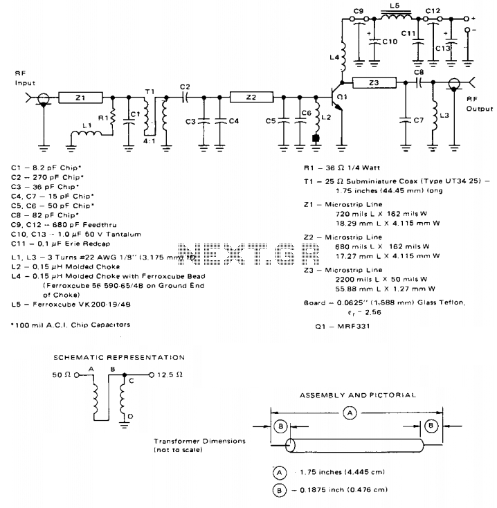
10w 225-400mhz linear amplifier
This broadband amplifier operates within the 225-400 MHz military communications band, delivering an RF output power of 10 watts while powered by a 28-volt supply. It is suitable for use as a driver for higher power devices such as the...
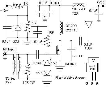
60watt rf radio frequency
The 60 Watt RF (Radio Frequency) Amplifier is a simple all-solid-state design utilizing the MOSFET IRF840. The IRF series of power transistors are available in various voltage and power ratings. A single IRF840 can handle a maximum power output of...
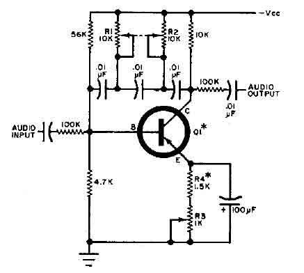
Q-multiplier filter circuit
This circuit is designed for selective tuning adjustments between two closely spaced audio tones. The frequency is determined by the values of the capacitors and resistors in the feedback circuit connecting the collector and base of transistor Q1. With the...
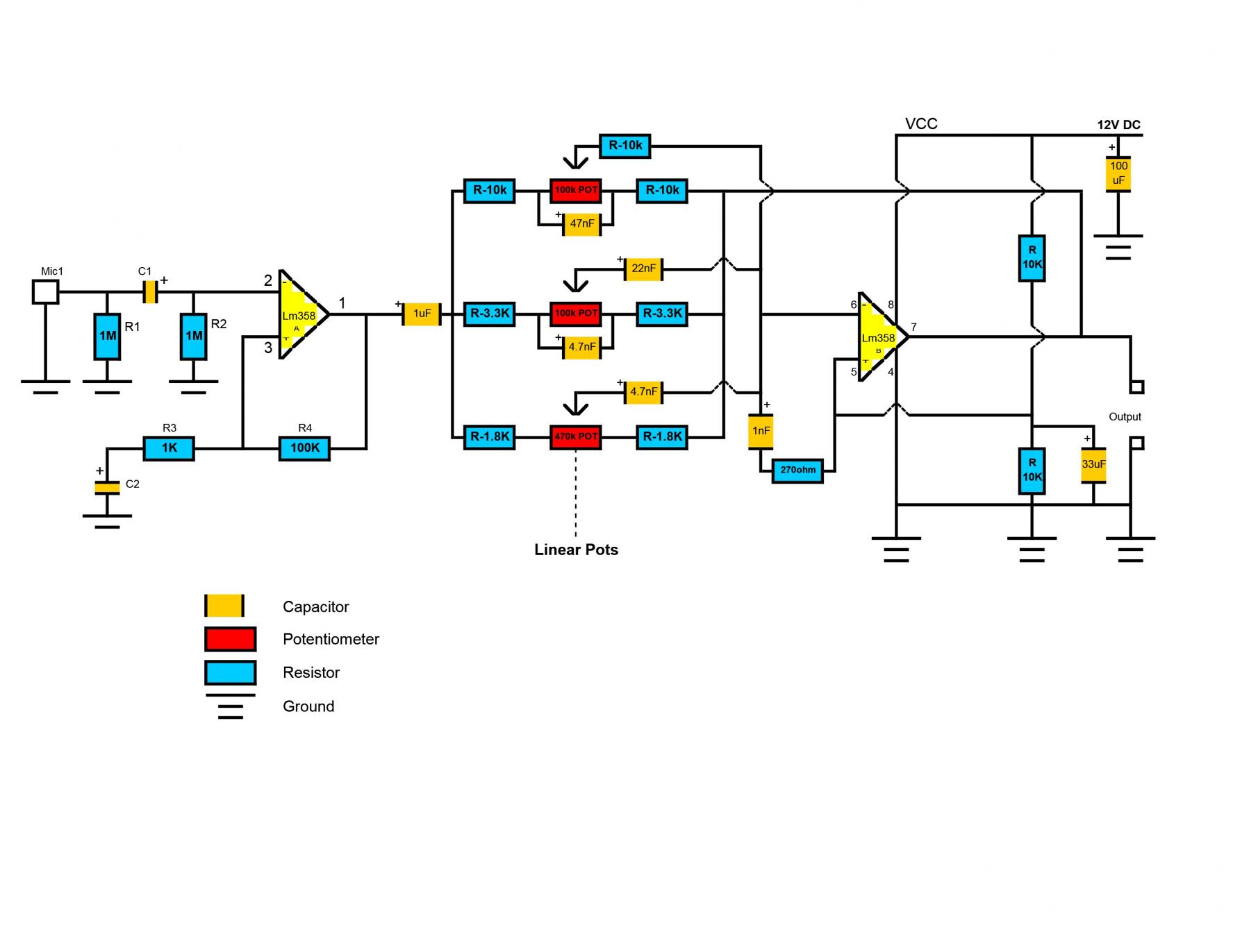
Custom DJ Karaoke Mixer/Scratch Pad/Laptop
After careful consideration and review of feedback, adjustments have been made to the project plans to include or remove certain functions. This project has already accumulated several developments.
The project in question appears to involve a systematic approach to electronic design,...
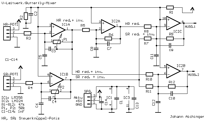
Butterfly Mixer Circuit
If the transmitter stick-potentiometer delivers a voltage about 2 - 3 V, this circuit will be suitable. If you want to avoid using the battery cable (supplying Vcc for IC1 and -2), you can use a separate 5V supply for...
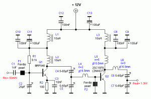
RF Amplifier circuit with 2SC1970 2N4427 Schematic Diagram
The RF power amplifier circuit described here utilizes the transistors 2SC1970 and 2N4427. This FM RF amplifier operates within the frequency range of 88-108 MHz, delivering an output power of approximately 1.3W from an input driver of 30-50mW. The RF...
Atv Video Sampler Circuit Circuit
This unit captures the ATV signal by sampling the transmission line with minimal insertion loss. It features two N connectors for input and output connections, and a BNC connector is utilized for the video output. The detected output is linked...