


max2659 gpsgnss low noise amplifier
#LNA
#GPS
#Galileo
#GLONASS
#SiGe
#low-noise amplifier
#RF amplifier
#signal amplification
#satellite navigation
#Maxim Integrated
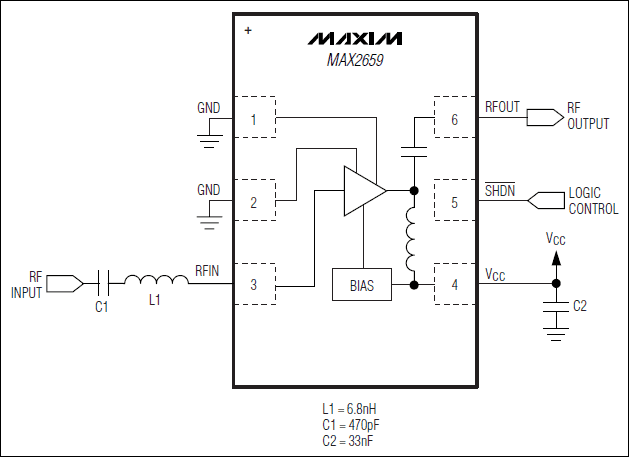
Description: The MAX2659 low-noise amplifier (LNA) is designed for GPS, Galileo, and GLONASS applications. Manufactured using Maxim's advanced SiGe process, the device achieves a gain of 20.5 dB and an ultra-low noise figure of 0.8 dB, while maximizing the input-referred 1 dB compression point and the 3rd-order intercept point at -12 dBm and -5 dBm, respectively. The MAX2659 operates from a +1.6V to +3.3V single supply and consumes only 4.1 mA. The shutdown feature in the device reduces the supply current to less than 1 µA. The MAX2659 is available in a very small, lead-free, RoHS compliant, 1.5 mm x 1.0 mm x 0.75 mm, 6-pin µDFN package.
The MAX2659 low-noise amplifier (LNA) is specifically engineered for high-performance applications in GPS, Galileo, and GLONASS systems. Utilizing Maxim Integrated's advanced silicon-germanium (SiGe) technology, the device is capable of delivering a substantial voltage gain of 20.5 dB while maintaining an exceptionally low noise figure of 0.8 dB. This performance is critical for enhancing signal integrity in sensitive RF environments.
The amplifier's design optimizes the input-referred 1 dB compression point at -12 dBm and the 3rd-order intercept point at -5 dBm, ensuring that the MAX2659 can handle a range of input signal levels without significant distortion. This characteristic is particularly beneficial in scenarios where high linearity is required, such as in multi-tone signals or in the presence of strong adjacent channels.
Power supply requirements for the MAX2659 are flexible, with operation supported over a voltage range of +1.6V to +3.3V. The device exhibits low power consumption, drawing only 4.1 mA during operation, which is advantageous for battery-powered applications. Additionally, the integrated shutdown feature allows the amplifier to reduce its supply current to less than 1 µA when not in use, further enhancing its efficiency and extending battery life.
The MAX2659 is packaged in a compact, lead-free, RoHS compliant 6-pin µDFN configuration, measuring 1.5 mm x 1.0 mm x 0.75 mm. This small footprint is ideal for integration into space-constrained designs, such as portable GPS modules or other RF applications where size and performance are critical. The combination of high gain, low noise, and efficient power management makes the MAX2659 an excellent choice for modern navigation systems.MAX2659 low-noise amplifier (LNA) is designed for GPS, Galileo, and GLONASS applications. Designed in Maxim`s advanced SiGe process, the device achieves a 20. 5dB gain and an ultra-low-noise figure of 0. 8dB while maximizing the input-referred 1dB compression point and the 3rd-order intercept point at -12dBm and -5dBm, respectively. The MAX2659 operates from a +1. 6V to +3. 3V single supply and consumes only 4. 1mA. The shutdown feature in the device reduces the supply current to be less than 1 µA. The MAX2659 is available in a very small, lead-free, Ro HS compliant, 1. 5mm x 1. 0mm x 0. 75mm, 6-pin µDFN package.
The MAX2659 low-noise amplifier (LNA) is specifically engineered for high-performance applications in GPS, Galileo, and GLONASS systems. Utilizing Maxim Integrated's advanced silicon-germanium (SiGe) technology, the device is capable of delivering a substantial voltage gain of 20.5 dB while maintaining an exceptionally low noise figure of 0.8 dB. This performance is critical for enhancing signal integrity in sensitive RF environments.
The amplifier's design optimizes the input-referred 1 dB compression point at -12 dBm and the 3rd-order intercept point at -5 dBm, ensuring that the MAX2659 can handle a range of input signal levels without significant distortion. This characteristic is particularly beneficial in scenarios where high linearity is required, such as in multi-tone signals or in the presence of strong adjacent channels.
Power supply requirements for the MAX2659 are flexible, with operation supported over a voltage range of +1.6V to +3.3V. The device exhibits low power consumption, drawing only 4.1 mA during operation, which is advantageous for battery-powered applications. Additionally, the integrated shutdown feature allows the amplifier to reduce its supply current to less than 1 µA when not in use, further enhancing its efficiency and extending battery life.
The MAX2659 is packaged in a compact, lead-free, RoHS compliant 6-pin µDFN configuration, measuring 1.5 mm x 1.0 mm x 0.75 mm. This small footprint is ideal for integration into space-constrained designs, such as portable GPS modules or other RF applications where size and performance are critical. The combination of high gain, low noise, and efficient power management makes the MAX2659 an excellent choice for modern navigation systems.MAX2659 low-noise amplifier (LNA) is designed for GPS, Galileo, and GLONASS applications. Designed in Maxim`s advanced SiGe process, the device achieves a 20. 5dB gain and an ultra-low-noise figure of 0. 8dB while maximizing the input-referred 1dB compression point and the 3rd-order intercept point at -12dBm and -5dBm, respectively. The MAX2659 operates from a +1. 6V to +3. 3V single supply and consumes only 4. 1mA. The shutdown feature in the device reduces the supply current to be less than 1 µA. The MAX2659 is available in a very small, lead-free, Ro HS compliant, 1. 5mm x 1. 0mm x 0. 75mm, 6-pin µDFN package.
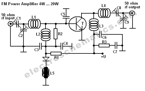
BLY94 50W RF Amplifier Circuit
This FM RF power amplifier circuit is constructed using a BLY94 transistor, which can deliver up to 50W at a frequency of 175MHz with a power gain of 7dB, resulting in approximately 5 times power amplification. However, in this schematic,...
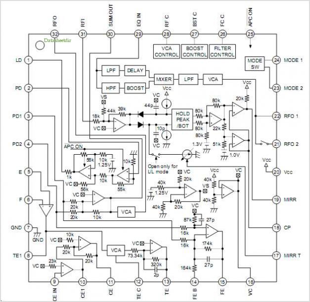
CXA2555Q Rf Amplifier For Cd Player/cd-rom
The CXG1024N is a high-power antenna switch MMIC designed to connect a transmitter/receiver (TX/RX) to one of four antennas. This integrated circuit (IC) is fabricated using Sony's GaAs J-FET process and operates with a single positive power supply.
The CXG1024N is...
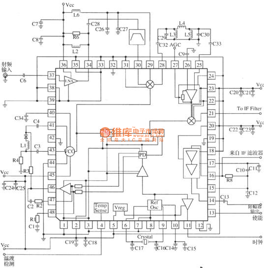
MRFICl505R2 based GPS receiver RF front-end circuit
MRFICl505R2 is a 1.575GHz GPS downconverter chip. It integrates a mixer, VCO, PLL, crystal oscillator, A/D converter, loop filter, and other circuits. The MRFICl505R2 IF output frequency is 4.1MHz, with a typical conversion gain of 105dB, an operating voltage of...
The KA7OEI FT-817 RF Power Amplifier
The 2SK2975 has reportedly been discontinued by the manufacturer, with the RD07MVS1 from Mitsubishi serving as its replacement. This new device is very similar but appears to have slightly higher gain—10 dB typical at 520 MHz compared to 8.4 dB...

Low-Noise 420Mhz Atv Receiver/Converter
Ll, Ql, L2, and L3 form an RF amplifier stage that feeds Ml, a doubly balanced mixer. Q4 is a local oscillator stage operating in the 375-MHz range. Signals in the 420- to 450-MHz range from Ql are mixed in...
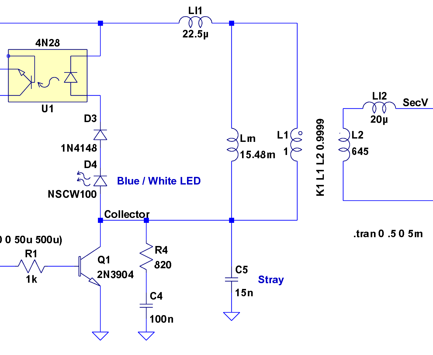
gps voice interface circuitry
The yellow wires on the far right serve as temporary power connections, allowing battery power to enter through the contact studs located in the large holes that press against the radio's battery terminals. The cable in the lower right is...
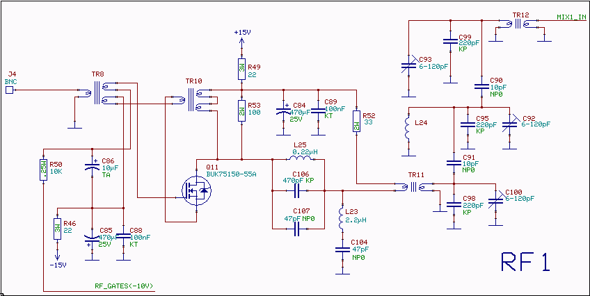
10.7 MHz RF Amplifier And Filter
The following circuit illustrates a 10.7 MHz RF amplifier and filter circuit diagram. Features include significant capacitances of a power MOSFET.
The 10.7 MHz RF amplifier and filter circuit is designed to amplify radio frequency signals while simultaneously filtering out unwanted...
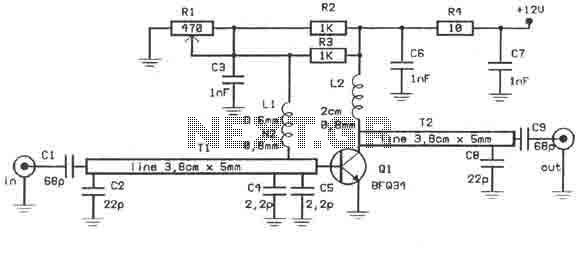
TV signal amplifier 470Mhz-860Mhz
This amplifier is designed to amplify RF signals from an antenna by 10 dB and operates as a Class A amplifier using the BFQ34 transistor from Philips. The BFQ34 is packaged in an SOT122A case. The BFQ34T variant is available...
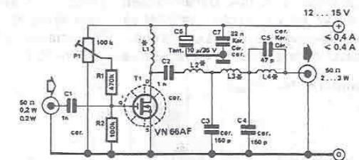
RF amplifier circuit diagram
By using this RF amplifier, small power transmitters of 200 mW can be upgraded to reasonable power transmitters, ranging between 2 and 3 W. The circuit is straightforward. The output filter network suppresses noise by at least 55 dB. The...