


N5ESE-built TenTec 1315/1330/1340
Description: Simple modifications have been made to these rigs to address some common shortcomings. Not all kits require these modifications, but many do. Some modifications resolve minor inconveniences, while others address potentially serious problems. For those who have previously built one of these kits and encountered issues, this page may provide helpful information. For individuals who have not built one yet and seek more information about the rig, a review of the Model 1340 is available. Additionally, specifications for the 13XX series can be found on TenTec's amateur radio site. The instructions for counting turns on toroid-wound inductors, as encountered in this kit and many others, can be confusing. Following the "by-word" instructions in the TenTec manuals alongside the provided drawings can lead to misunderstanding. To clarify, when winding a toroid coil, the first turn involves inserting one end of the wire straight through the center of the core without bending it. This constitutes "turn 1." The wire is then bent around the outside of the core and inserted through the center again, resulting in "2 turns." The wire should be pulled tight so that it lies flat against the core, with one end sticking out in one direction and the other end starting from the opposite side. Counting the wires against the inside of the core results in "2," while counting the wires on the outside yields "1." Therefore, a "2-turn" coil is created, and if TenTec specifies winding a toroid coil with 6 turns, one would count 5 on the outside edge and 6 "passes" on the inside. This is a common coil-winding convention, illustrated below. One of the most frequently required modifications for this series of transceivers addresses a problem that, while not present in all kits, is commonly encountered by builders of the TenTec 1300 series kit, as indicated by inquiries on mailing lists over the years. In personal experience, this issue arose in all three kits constructed (the 40, 30, and 15-Meter models), and implementing this modification resolved the issue in each case. It is advisable to incorporate this modification during assembly to avoid disassembly later. Symptoms of the problem include a loud hiss or buzz in the sidetone when keying, along with an increase in SWR (measured in the output circuit). Output power may fluctuate, but it is not advisable to transmit under these conditions. Initially, there was a suspicion of low-frequency parasitic oscillation in the final amplifier; however, it is now believed to be a near-frequency oscillation rich in harmonics. The partially self-biased final amplifier may contribute to its susceptibility to oscillation, but the primary cause appears to stem from the printed-circuit board layout. Although the overall PCB layout is satisfactory, it seems that compromises were made due to space limitations during the design of the final stage, leading to potential coupling between the three toroid-wound inductors in the final's low-pass filter and matching network (L8, L9, L10), the matching transformer T1, and the driver’s inductor L15. This design flaw makes the final amplifier prone to near-frequency oscillation when the output match is not perfectly resistive, and at times, even when it is. An SWR meter connected to the output circuit will indicate a rising SWR, and achieving a zero SWR will be impossible due to a significant portion of the oscillation energy being at harmonics.
The modifications to the TenTec 1300 series transceiver kits primarily focus on addressing the oscillation issues stemming from the PCB layout and the coupling of inductors within the final amplifier section. The suggested approach involves enhancing the isolation between the inductors and ensuring that the layout minimizes parasitic interactions. This can be achieved through careful re-routing of traces, adding shielding where necessary, and potentially adjusting the values of the inductors to achieve a better match.
Furthermore, it may be beneficial to assess the grounding scheme employed in the design. Ensuring a solid ground connection across all components can help mitigate unwanted oscillations. Additionally, implementing bypass capacitors close to the power and output stages can help filter out high-frequency noise that may contribute to instability.
For builders, incorporating these modifications during the initial assembly process is crucial. It not only saves time but also enhances the overall performance and reliability of the transceiver. Proper documentation of each modification should be maintained for future reference, as well as for sharing with the builder community to assist others who may encounter similar issues. This proactive approach will lead to a more robust and enjoyable user experience with the TenTec 1300 series kits.Simple modifications I`ve done on these rigs, to overcome some common shortcomings. Not all kits need these mods, but many do. Some overcomeminor inconveniences, and some potentially serious problems. If you have built one of these kits before, and encountered problems, I hope this page will help. If you have not built one, and would like more information about the rig in general, read my review of the Model 1340 -here-. And you can find the 13XX`s specs at TenTec`s amateur radio site -here- If you ever wanted to be confused about counting turns on toroid-wound inductors (such as encountered in this kit and many others), all you need to do is try to follow the "by-word" instructions in the TenTec manuals, then look at the drawings they provide. aaAARRGH! This can really mess with your mind. Here`s my attempt to stir the water and make it clear as mud. Pick up a toroid core in your left hand, and a piece of wire in your right. Stick one end of the wire straight through the center of the core, without bending it. This is turn "1". Now, bend it around the outside of the core, and again stick the end through the center of the core. That`s "2" turns. Pull it tight, so the wire lays flat against the core all the way around, and the wire is sticking out in one direction, while starting from the exact opposite.
If you count the wires laying against the inside of the core, you`ll count "2". If you count the wires on the outside of the core, you`ll count "1". This is a "2-turn" coil, and this is how TenTec wants you to count turns. So, if TenTec asks you to wind a toroid coil with 6 turns, you`ll count 5 on the outside edge, and 6 "passes" on the inside. This is a common coil-winding convention, and you can see this illustrated below: This mod is probably the most commonly required mod with this series of transceiver.
Although the problem it cures is not encountered in all kits, and maybe not even most, it is still the most common problem encountered by builders of the TenTec 1300 series kit (as evidenced by the questions on maillists I have frequented over the years). In my case, I encountered the problem on all three of the kits I built (the 40, 30 and 15-Meter models), and this mod fixed them all.
If you`ve not built your kit yet, I suggest you incorporate this modification as you build it, and avoid having to disassemble later. The symptoms are as follows: When keying, the sidetone will be a loud hissy or buzzy sound, and the SWR (measured in the output circuit) will increase.
The output power may go up or down, but I assure you, you don`t want to transmit with this condition. At first I thought this was a low-frequency parasitic oscillation in the final amplifier, but lately I have been given to believe it is a near-frequency oscillation, rich in harmonics.
The partially self-biased final may contribute to the susceptability of the final to oscillate (that mod later), but the root cause is printed-circuit board layout. The pc layout is pretty good all around, but it seems as if the TenTec designer ran out of board space as the final was being layed out, and serious compromises were made.
The end result is that the three toroid-wound inductors in the final`s low-pass filter and matching network (L8, L9, L10), can couple into each other and matching transformer T1, and the driver`s L15. This makes the final amplifier prone to break into near-frequency oscillation when the output match is not perfectly resistive (and sometimes, even when it is).
If you have an SWR meter in your output circuit, you`ll see the SWR rise, and you wan`t be able to make the SWR go to zero, because a significant part of the oscillation energy is at harmonics. Sometimes, if you pre-tune to p
The modifications to the TenTec 1300 series transceiver kits primarily focus on addressing the oscillation issues stemming from the PCB layout and the coupling of inductors within the final amplifier section. The suggested approach involves enhancing the isolation between the inductors and ensuring that the layout minimizes parasitic interactions. This can be achieved through careful re-routing of traces, adding shielding where necessary, and potentially adjusting the values of the inductors to achieve a better match.
Furthermore, it may be beneficial to assess the grounding scheme employed in the design. Ensuring a solid ground connection across all components can help mitigate unwanted oscillations. Additionally, implementing bypass capacitors close to the power and output stages can help filter out high-frequency noise that may contribute to instability.
For builders, incorporating these modifications during the initial assembly process is crucial. It not only saves time but also enhances the overall performance and reliability of the transceiver. Proper documentation of each modification should be maintained for future reference, as well as for sharing with the builder community to assist others who may encounter similar issues. This proactive approach will lead to a more robust and enjoyable user experience with the TenTec 1300 series kits.Simple modifications I`ve done on these rigs, to overcome some common shortcomings. Not all kits need these mods, but many do. Some overcomeminor inconveniences, and some potentially serious problems. If you have built one of these kits before, and encountered problems, I hope this page will help. If you have not built one, and would like more information about the rig in general, read my review of the Model 1340 -here-. And you can find the 13XX`s specs at TenTec`s amateur radio site -here- If you ever wanted to be confused about counting turns on toroid-wound inductors (such as encountered in this kit and many others), all you need to do is try to follow the "by-word" instructions in the TenTec manuals, then look at the drawings they provide. aaAARRGH! This can really mess with your mind. Here`s my attempt to stir the water and make it clear as mud. Pick up a toroid core in your left hand, and a piece of wire in your right. Stick one end of the wire straight through the center of the core, without bending it. This is turn "1". Now, bend it around the outside of the core, and again stick the end through the center of the core. That`s "2" turns. Pull it tight, so the wire lays flat against the core all the way around, and the wire is sticking out in one direction, while starting from the exact opposite.
If you count the wires laying against the inside of the core, you`ll count "2". If you count the wires on the outside of the core, you`ll count "1". This is a "2-turn" coil, and this is how TenTec wants you to count turns. So, if TenTec asks you to wind a toroid coil with 6 turns, you`ll count 5 on the outside edge, and 6 "passes" on the inside. This is a common coil-winding convention, and you can see this illustrated below: This mod is probably the most commonly required mod with this series of transceiver.
Although the problem it cures is not encountered in all kits, and maybe not even most, it is still the most common problem encountered by builders of the TenTec 1300 series kit (as evidenced by the questions on maillists I have frequented over the years). In my case, I encountered the problem on all three of the kits I built (the 40, 30 and 15-Meter models), and this mod fixed them all.
If you`ve not built your kit yet, I suggest you incorporate this modification as you build it, and avoid having to disassemble later. The symptoms are as follows: When keying, the sidetone will be a loud hissy or buzzy sound, and the SWR (measured in the output circuit) will increase.
The output power may go up or down, but I assure you, you don`t want to transmit with this condition. At first I thought this was a low-frequency parasitic oscillation in the final amplifier, but lately I have been given to believe it is a near-frequency oscillation, rich in harmonics.
The partially self-biased final may contribute to the susceptability of the final to oscillate (that mod later), but the root cause is printed-circuit board layout. The pc layout is pretty good all around, but it seems as if the TenTec designer ran out of board space as the final was being layed out, and serious compromises were made.
The end result is that the three toroid-wound inductors in the final`s low-pass filter and matching network (L8, L9, L10), can couple into each other and matching transformer T1, and the driver`s L15. This makes the final amplifier prone to break into near-frequency oscillation when the output match is not perfectly resistive (and sometimes, even when it is).
If you have an SWR meter in your output circuit, you`ll see the SWR rise, and you wan`t be able to make the SWR go to zero, because a significant part of the oscillation energy is at harmonics. Sometimes, if you pre-tune to p
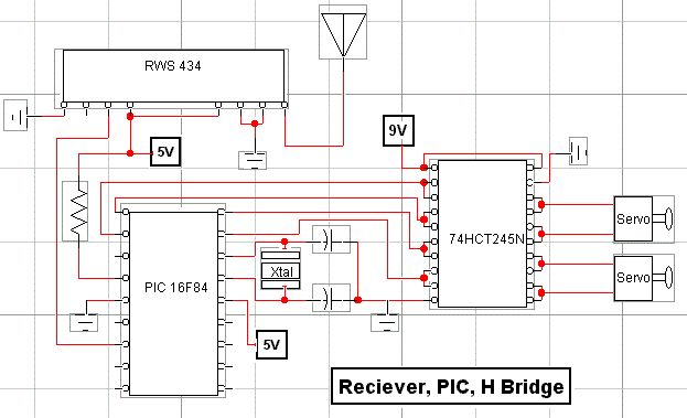
rf modem robotics project using pic16f84 microcontroller
RF technology is an exciting field to incorporate into electronic designs. However, for beginners, constructing reliable RF transmitters and receivers can be challenging.
RF (Radio Frequency) technology plays a crucial role in modern communication systems, enabling wireless data transmission over various...
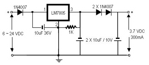
how to convert a 9v battery to 3.7v
A regulator circuit is needed for this DIY project. Familiarity with electronic components, circuitry, the use of a multitester, and a soldering iron is essential. The schematic diagram provided can accept an input voltage ranging from 6 to 24 volts...
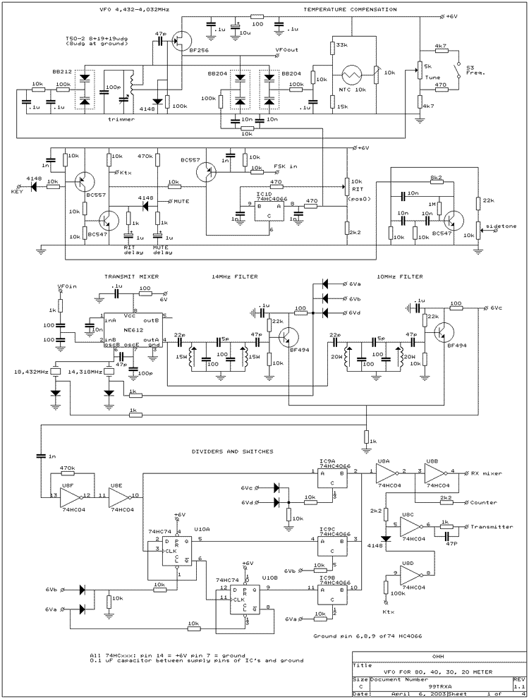
FOUR BAND CW TRANSCEIVER WITH DIRECT CONVERSION
The performance of the 80-meter CW transceiver using the phase method for sideband suppression is very good. Construction was easy with all standard electronic components available, without the need for an expensive or complex crystal filter. Almost no signals are...
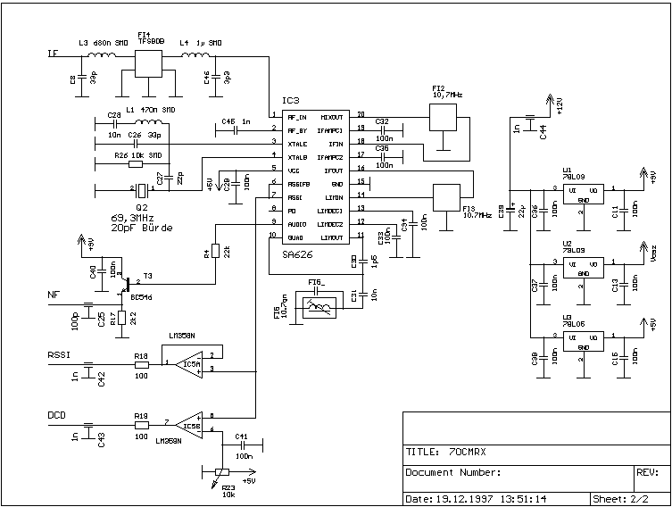
A 70cm Wide-band Transceiver Concept
This article provides a detailed overview of a 70 cm wideband transceiver designed for duplex operation. The modules operate within a 200 kHz wide duplex channel, selectable from 430-440 MHz with a 100 kHz channel spacing. Initial prototypes were introduced...
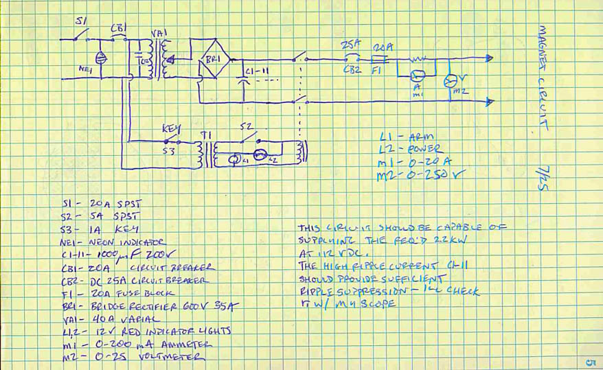
Cyclotron II
The white feedthroughs are for connecting the RF high voltage to the D's (not shown). The copper pipe perpendicular to the main pipe serves as the vacuum line. The D's are equipped with screw posts on the side for connecting...
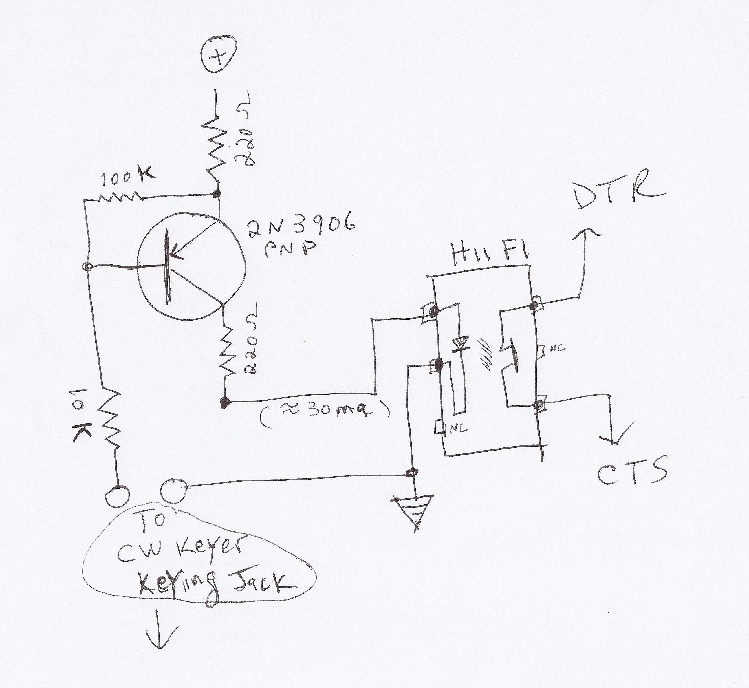
using virtual serial ports for ham radio dahdidah cw keyer
This video demonstrates how to initiate multiple instances of QsoNet's Dahdidah CW Software Keyer using FABULATECH's Virtual Serial Port Splitter. Four separate...
The QsoNet Dahdidah CW Software Keyer is a sophisticated tool designed for amateur radio operators, allowing them to send...
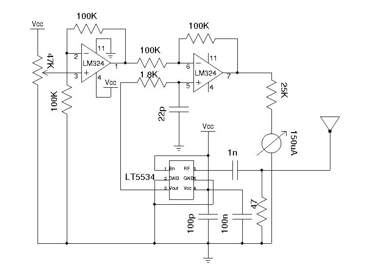
Wideband RF Field Strength Meter
A field strength meter is highly beneficial when dealing with RF devices. It allows for the rapid diagnosis of transmitter circuit functionality and can detect RF signals present in the environment. The simplest form of a field strength meter can...
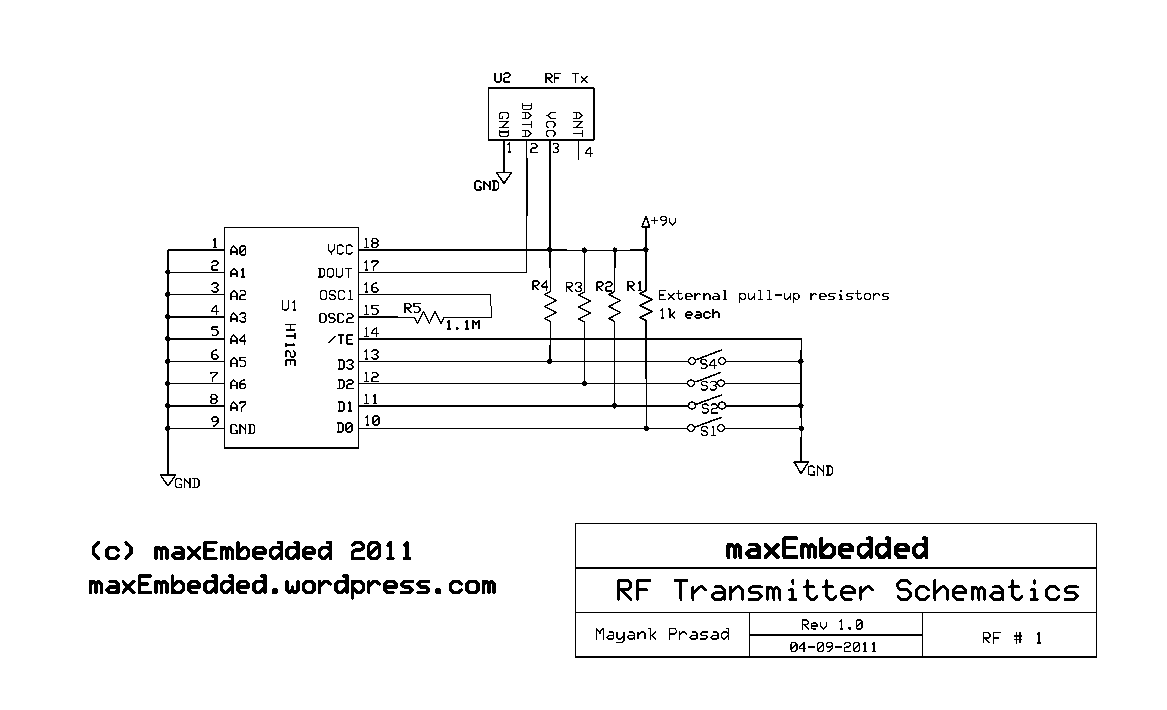
making an rf car
This article is authored by Yash Tambi, a Core Committee Member of roboVITics. It discusses RF-controlled robots, which are among the simplest types of robots. The essential components include a few readily available integrated circuits (ICs), a 433 MHz transmitter...
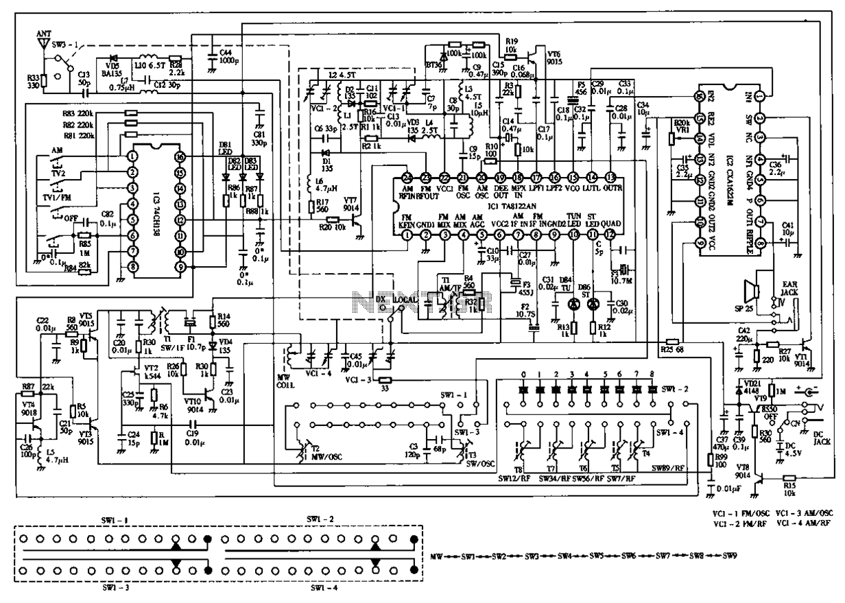
Desheng 119 700 High sensitivity l2-band stereo radio circuit diagram
The circuit diagram for the Desheng 119 700 type FM, TV sound, medium wave, and short wave high sensitivity L2-band stereo radio is presented below.
The Desheng 119 700 type radio circuit is designed to receive various frequency bands including FM,...