


Narrow-band-fm-receiver
#narrow-band
#fm receiver
#crystal-controlled
#local oscillator
#i-f bandwidth
#demodulated audio
#all-pass filters
#modulation
#carrier frequency
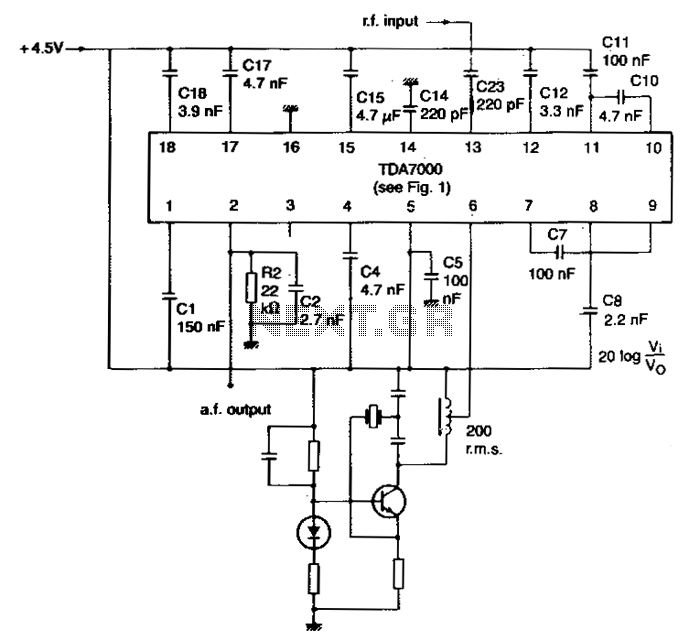
Description: The local oscillator is controlled by a crystal, and the intermediate frequency (i-f) swing is minimally compressed. To prevent significant distortion of the demodulated audio signal, the deviation of the transmitted carrier frequency due to modulation must be limited. The component values yield an i-f of 4.5 kHz and an i-f bandwidth of 5 kHz. If the i-f is multiplied by a factor of N, the values of capacitors C17 and C18 in the all-pass filters, along with the values of filter capacitors C7, C8, C10, C11, and C12, must be scaled by 1/N. For enhanced i-f selectivity and improved adjacent channel attenuation, second-order networks can be employed instead of C10 and C11.
The described circuit utilizes a crystal-controlled local oscillator to maintain frequency stability, which is crucial for effective modulation and demodulation processes. The intermediate frequency (i-f) is set at 4.5 kHz, with a bandwidth of 5 kHz, allowing for adequate signal processing while minimizing the risk of distortion. The modulation process introduces a deviation in the carrier frequency; thus, careful management of this deviation is essential to preserve the integrity of the audio signal after demodulation.
In scenarios where the i-f is multiplied by a factor of N, adjustments to the capacitors are necessary to maintain circuit performance. Specifically, capacitors C17 and C18 in the all-pass filters, as well as filter capacitors C7, C8, C10, C11, and C12, must be resized according to the factor of 1/N. This scaling ensures that the frequency response of the circuit remains consistent with the new i-f.
To enhance selectivity and achieve better adjacent channel attenuation, the circuit can incorporate second-order filter networks in place of the standard first-order filters represented by capacitors C10 and C11. Second-order networks provide sharper roll-off characteristics, improving the circuit's ability to reject unwanted signals from adjacent channels, thus enhancing overall system performance and audio clarity. This design consideration is critical in applications where signal integrity and clarity are paramount.The local oscillator is crystal-controlled and the i-f swing is hardly compressed. The deviation of the transmitted carrier frequency, because of modulation, must therefore be limited to prevent severe distortion of the demodulated audio signal. The component values result in an i-f of 4.5 kHz and an i-f bandwidth of 5kHz. If the i-f is multiplied ll"f N, the values of capacitors Cl7 and Cl8 in the all-pass filters, and the values of illter capacitors C7, CS, ClO, Cll, and Cl2 must be multiplied by 1/N.
For improved i-f selectivity to achieve greater adjacent channel attenuation, second-order networks can be used in place of ClO and Cll.
The described circuit utilizes a crystal-controlled local oscillator to maintain frequency stability, which is crucial for effective modulation and demodulation processes. The intermediate frequency (i-f) is set at 4.5 kHz, with a bandwidth of 5 kHz, allowing for adequate signal processing while minimizing the risk of distortion. The modulation process introduces a deviation in the carrier frequency; thus, careful management of this deviation is essential to preserve the integrity of the audio signal after demodulation.
In scenarios where the i-f is multiplied by a factor of N, adjustments to the capacitors are necessary to maintain circuit performance. Specifically, capacitors C17 and C18 in the all-pass filters, as well as filter capacitors C7, C8, C10, C11, and C12, must be resized according to the factor of 1/N. This scaling ensures that the frequency response of the circuit remains consistent with the new i-f.
To enhance selectivity and achieve better adjacent channel attenuation, the circuit can incorporate second-order filter networks in place of the standard first-order filters represented by capacitors C10 and C11. Second-order networks provide sharper roll-off characteristics, improving the circuit's ability to reject unwanted signals from adjacent channels, thus enhancing overall system performance and audio clarity. This design consideration is critical in applications where signal integrity and clarity are paramount.The local oscillator is crystal-controlled and the i-f swing is hardly compressed. The deviation of the transmitted carrier frequency, because of modulation, must therefore be limited to prevent severe distortion of the demodulated audio signal. The component values result in an i-f of 4.5 kHz and an i-f bandwidth of 5kHz. If the i-f is multiplied ll"f N, the values of capacitors Cl7 and Cl8 in the all-pass filters, and the values of illter capacitors C7, CS, ClO, Cll, and Cl2 must be multiplied by 1/N.
For improved i-f selectivity to achieve greater adjacent channel attenuation, second-order networks can be used in place of ClO and Cll.
carrier current fm receiver
Input signals from the power line are coupled through C23 and R19 to the input filter network. C23 must be rated at 600 volts. Switch 52 is used as an attenuator. Components C2 through C7, L1 through L3, R1, and...
fm receiver basics
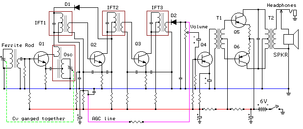
FM receivers are primarily of the superheterodyne type. To understand FM radio receivers, it is essential to consider the key differences between AM and FM signals. While it may seem obvious, these differences are significant. An AM receiver depends on...
Electronic Transformers Modulation
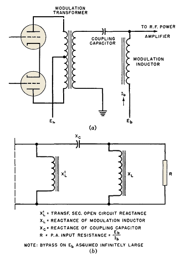
Wave-filter principles are utilized in various circuits beyond filters, such as in the design of modulation transformers for high-level amplitude-modulated radio transmitters. Some of these transformers are quite large. In plate-modulated power amplifiers, the modulator power necessary for achieving 100...
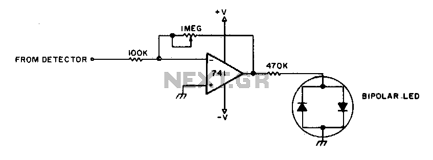
Zero center indicator for FM receivers
To adjust, tune into a station and adjust the I"M pot for a null. Then ask the station to modulate and fine-tune so modulation peaks do not light the LEDs. Stations are properly tuned when neither LED is lit.
The circuit...
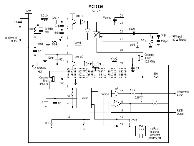
FM reciever with MC13136
One of the circuits used in projects is the MC13135/MC13136. It is the second generation of single-chip, dual-conversion FM communication receivers developed by Motorola. Major improvements in signal handling, RSSI, and first oscillator operation have been made. At pin 22,...
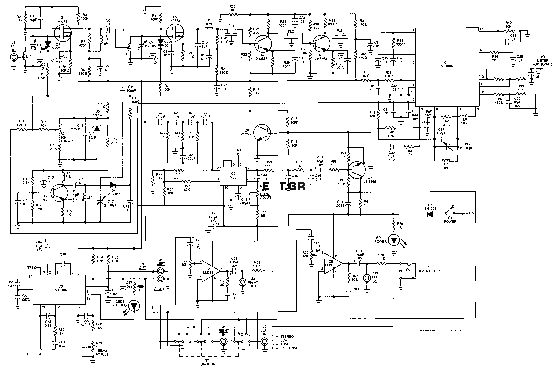
Fm-mpx-sca-receiver
This receiver is capable of better than 1.5 pV IHF sensitivity and uses MOSFET front-end circuitry with varactors to eliminate conventional bulky tuning capacitors. It also features a high dynamic range, ceramic IF filters requiring no alignment, and a quadrature-type...
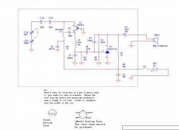
One Transistor FM Receiver circuit diagram
This is a very simple FM receiver built using only one transistor. It does not utilize any chips or other active components. The output is connected to earphones; an amplifier circuit is required if the radio is to be heard...
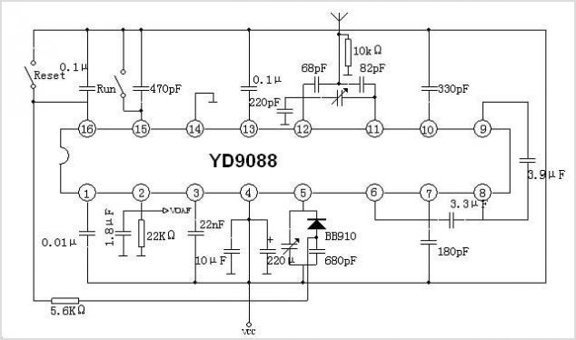
YD9088 FM RECEIVER CIRCUIT FOR BATTERY SUPPLY
Zilog's Z8 Encore XP F1680 Series features a highly optimized set of capabilities specifically designed for stepper motor microstepping control. Key features of the Z8 Encore! XP F1680 include: an 11 MHz internal oscillator, two analog comparators, a 10-bit analog-to-digital...
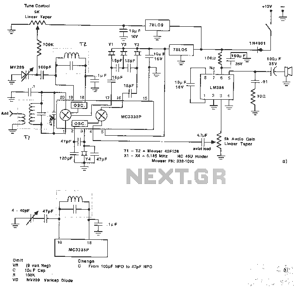
Receiver schematic design using MC3335PSSB
The MC3335P is a low-power narrowband FM receiver that can be used to design a very simple 80 m SSB receiver. The MC3335 also features a comparator circuit for FSK detection. The circuit is straightforward and requires few external components,...