


Phase demodulation
#phase demodulation
#quadrature signal
#transmitter
#master oscillator
#phase reference
#detector
#RF
#signal processing
#modulation
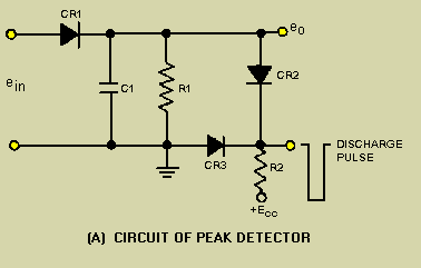
Description: The quadrature-grid signal is driven by a reference from the transmitter. This reference may consist of a sample of the unmodulated master oscillator, which provides a phase reference for the detector. The modulated waveform is applied to the limiter grid. Gating action in the tube occurs as the phase shifts between the input waveform and the reference. The combined output current from the gated-beam tube generates a series of current pulses. The width of these pulses varies according to the phase difference between the carrier and the modulated wave.
In the described electronic circuit, the quadrature-grid signal plays a crucial role in phase detection and modulation processes. The reference signal, typically sourced from an unmodulated master oscillator, serves as a stable phase reference for the detection system. This configuration is essential in applications such as phase-locked loops and demodulation systems where precise phase relationships are critical.
The limiter grid receives the modulated waveform, which is subjected to gating action within the tube. This gating action is a result of the phase relationship between the incoming modulated signal and the reference signal. As the phase shifts, the gated-beam tube selectively allows current to pass, resulting in the output of current pulses. The characteristics of these pulses, particularly their width, are directly influenced by the phase difference between the carrier wave and the modulated waveform.
The output current pulses can be analyzed to extract information about the modulated signal, making this system particularly useful in communication systems where phase modulation is employed. The varying pulse widths can be visualized in a graphical representation, such as figure 3-20, which illustrates how the pulse width changes in response to different phase relationships. This behavior is critical for ensuring accurate signal interpretation and maintaining the integrity of the transmitted information.
In summary, the interaction between the quadrature-grid signal, the reference oscillator, and the modulated waveform is fundamental to the operation of the gated-beam tube, facilitating effective modulation and demodulation processes in electronic communication systems.The quadrature-grid signal is excited by a reference from the transmitter. This may be a sample of the unmodulated master oscillator providing a phase reference for the detector. The modulated waveform is applied to the limiter grid. Gating action in the tube will occur as the phase shifts between the input waveform and the reference. The combined output current from the gated-beam tube will be a series of current pulses. These pulses will vary in width as shown in figure 3-20. The width of these pulses will vary in accordance with the phase difference between the carrier and the modulated wave.
In the described electronic circuit, the quadrature-grid signal plays a crucial role in phase detection and modulation processes. The reference signal, typically sourced from an unmodulated master oscillator, serves as a stable phase reference for the detection system. This configuration is essential in applications such as phase-locked loops and demodulation systems where precise phase relationships are critical.
The limiter grid receives the modulated waveform, which is subjected to gating action within the tube. This gating action is a result of the phase relationship between the incoming modulated signal and the reference signal. As the phase shifts, the gated-beam tube selectively allows current to pass, resulting in the output of current pulses. The characteristics of these pulses, particularly their width, are directly influenced by the phase difference between the carrier wave and the modulated waveform.
The output current pulses can be analyzed to extract information about the modulated signal, making this system particularly useful in communication systems where phase modulation is employed. The varying pulse widths can be visualized in a graphical representation, such as figure 3-20, which illustrates how the pulse width changes in response to different phase relationships. This behavior is critical for ensuring accurate signal interpretation and maintaining the integrity of the transmitted information.
In summary, the interaction between the quadrature-grid signal, the reference oscillator, and the modulated waveform is fundamental to the operation of the gated-beam tube, facilitating effective modulation and demodulation processes in electronic communication systems.The quadrature-grid signal is excited by a reference from the transmitter. This may be a sample of the unmodulated master oscillator providing a phase reference for the detector. The modulated waveform is applied to the limiter grid. Gating action in the tube will occur as the phase shifts between the input waveform and the reference. The combined output current from the gated-beam tube will be a series of current pulses. These pulses will vary in width as shown in figure 3-20. The width of these pulses will vary in accordance with the phase difference between the carrier and the modulated wave.
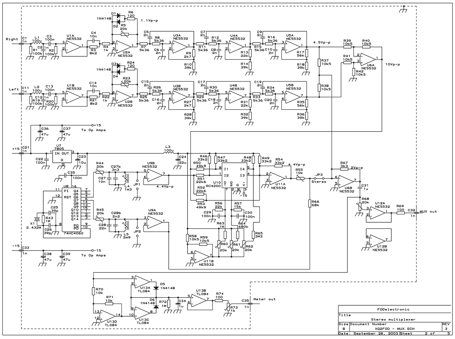
80 Watt stereo transmitter
This transmitter was designed from the ground up to provide very high sound quality, coupled with excellent frequency stability, reliability, etc. It can be used as a standalone transmitter to serve a medium-sized town, or as an exciter to drive...
RF-Radio Frequency 6
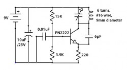
This circuit is designed to attenuate signal frequency, with a customizable range from 1 to 40 dB. For UHF band usage, it should be enclosed within a shielded frame, and capacitors C1 to C3 should be appropriately selected. The connection...
tv transmitter circuit
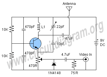
Here is a simple schematic of a TV transmitter circuit, or video transmitter circuit, capable of broadcasting in the VHF range from 60 to 200 MHz. The input video source can be any CCD camera or VCR. The output power...
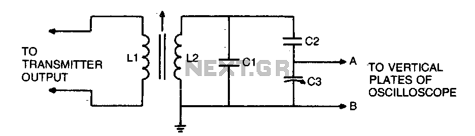
Transmitter-oscilloscope coupler for CB signals
To display an RF signal, connect LI to the transmitter and points A and B to the vertical plates of the oscilloscope. Adjust LI for minimum SWR and C3 for the desired trace height on the CRT. More: L2 consists...
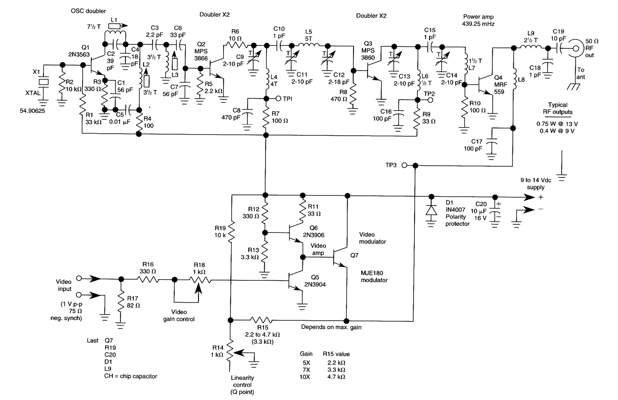
ATV JR TRANSMITTER 440 MHz
This low-power video transmitter is suitable for remote control applications, surveillance, or amateur radio. It employs seven transistors within a crystal oscillator multiplier RF power amplifier chain, along with a high-level video modulator. A supply voltage ranging from 9 to...
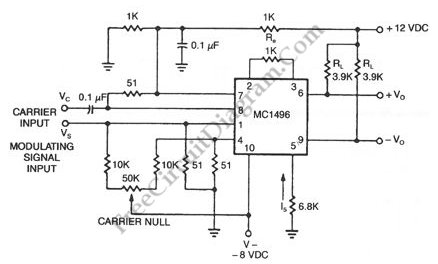
Double-Sideband Suppressed-Carrier (DSB-SC) Modulator
When a carrier signal is modulated using amplitude modulation, four frequency components are produced. The first component is the modulating signal itself, the second is the carrier frequency, while the last two are the sum and difference of the carrier...
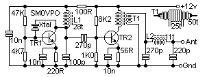
CW 250mW transmitter
Here is a simple little HF TX. It may be modified for all the HF bands, but the details given are only for the 7MHz band. The basic transmitter uses two transistors; BC547 (as usual) and will deliver over 250mW...
field strength meter fsm
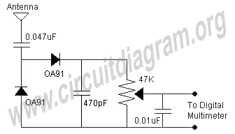
A field strength meter circuit is a valuable device for measuring the RF output of any transmitter or for experimenting with different antennas connected to the transmitter. The operation of the field strength meter (FSM) is straightforward; it converts RF...
Remote ControlCircuit Through RF Without Microcontroller
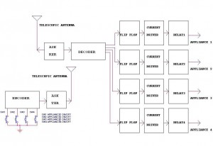
This circuit illustrates a remote control circuit diagram using RF technology without the use of a microcontroller. Features include a simple remote control circuit that operates via radio frequency.
The remote control circuit operates by transmitting signals through radio waves, enabling...