


Phase-detector
#phase-detector
#frequency
#cosine
#signals
#filter
#RF
#phase angle
#multiplier
#difference component
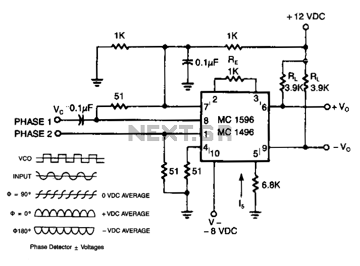
Description: The output of the detector includes a term associated with the cosine of the phase angle. Two signals of equal frequency are applied to the inputs. These frequencies are multiplied, resulting in both sum and difference frequencies. When the frequencies are equal, the difference component becomes direct current (DC), while the unwanted sum component is filtered out. The DC component is linked to the phase angle as illustrated in Fig. 70-2B. At 90 degrees, the cosine value is zero, while it reaches maximum positive and maximum negative values at 0 degrees and 180 degrees, respectively. The advantage of utilizing the balanced modulator over other types of phase comparators lies in its excellent conversion linearity. This configuration also yields a conversion gain, enhancing resolution rather than causing a loss. When used with a phase-locked loop, the balanced modulator serves as a very low-distortion frequency modulation (FM) demodulator. Correct phase sequences (ABC, BCA, or CAB) generate trains of output pulses that illuminate the LED. Conversely, the output remains low and the LED stays dark for incorrect sequences (BAC, ACB, or CBA) or in cases of phase loss (when phase A, B, or C is missing).
The described circuit operates by leveraging the properties of phase comparison and modulation to achieve reliable signal processing. The balanced modulator functions by taking two input signals of the same frequency and performing multiplication, which leads to the generation of sum and difference frequencies. The desired difference frequency is processed to yield a DC output, effectively representing the phase relationship between the two input signals. The cosine function's behavior at various phase angles is critical for understanding how the output varies; specifically, it is important to note that at 90 degrees, there is no output, while maximum outputs occur at 0 and 180 degrees.
The balanced modulator's linearity ensures that the output is proportional to the phase difference, which is advantageous in applications requiring precise phase measurements. The conversion gain provided by this configuration enhances the signal resolution, making it suitable for applications such as FM demodulation. When integrated with a phase-locked loop, the modulator can effectively track and demodulate frequency-modulated signals with minimal distortion, thereby improving the overall fidelity of the received signal.
In terms of output behavior, the circuit is designed to respond to specific phase sequences. Correct sequences result in a high output signal that activates an LED, providing a visual indication of proper operation. Conversely, incorrect phase sequences or the absence of any phase input leads to a low output, keeping the LED off. This feature is crucial for applications where phase integrity is vital, as it allows for immediate feedback regarding system performance. The ability to detect phase loss enhances the reliability of the circuit in practical applications, ensuring that any issues can be promptly addressed.The output of the detector contains a term related to the cosine of the phase angle. Two signals of equal frequency are applied to the inputs. The frequencies are multiplied together, producing the sum and difference frequencies. Equal frequencies cause the difference component to become de, while the undesired sum component is filtered out. The de component is related to the phase angle by the graph of Fig. 70-2B. At 90°, the cosine becomes zero, while being at maximum positive or maximum negative at 0° and 180°, respectively.
The advantage of using the balanced modulator over other types of phase comparators is the excellent conversion linearity. This configuration also provides a conversion gain, rather than a loss for greater resolution. Used in conjunction with a phase-locked loop, for instance, the balanced modulator provides a very low-distortion FM demodulator.
Correct phase sequences (ABC, BCA, or CAB) produce trains of output pulses and illuminate the LED. The output stays low and the LED remains dark for incorrect sequences (BAC, ACB, or CBA) or for phase loss (phase A, B, or C missing).
The described circuit operates by leveraging the properties of phase comparison and modulation to achieve reliable signal processing. The balanced modulator functions by taking two input signals of the same frequency and performing multiplication, which leads to the generation of sum and difference frequencies. The desired difference frequency is processed to yield a DC output, effectively representing the phase relationship between the two input signals. The cosine function's behavior at various phase angles is critical for understanding how the output varies; specifically, it is important to note that at 90 degrees, there is no output, while maximum outputs occur at 0 and 180 degrees.
The balanced modulator's linearity ensures that the output is proportional to the phase difference, which is advantageous in applications requiring precise phase measurements. The conversion gain provided by this configuration enhances the signal resolution, making it suitable for applications such as FM demodulation. When integrated with a phase-locked loop, the modulator can effectively track and demodulate frequency-modulated signals with minimal distortion, thereby improving the overall fidelity of the received signal.
In terms of output behavior, the circuit is designed to respond to specific phase sequences. Correct sequences result in a high output signal that activates an LED, providing a visual indication of proper operation. Conversely, incorrect phase sequences or the absence of any phase input leads to a low output, keeping the LED off. This feature is crucial for applications where phase integrity is vital, as it allows for immediate feedback regarding system performance. The ability to detect phase loss enhances the reliability of the circuit in practical applications, ensuring that any issues can be promptly addressed.The output of the detector contains a term related to the cosine of the phase angle. Two signals of equal frequency are applied to the inputs. The frequencies are multiplied together, producing the sum and difference frequencies. Equal frequencies cause the difference component to become de, while the undesired sum component is filtered out. The de component is related to the phase angle by the graph of Fig. 70-2B. At 90°, the cosine becomes zero, while being at maximum positive or maximum negative at 0° and 180°, respectively.
The advantage of using the balanced modulator over other types of phase comparators is the excellent conversion linearity. This configuration also provides a conversion gain, rather than a loss for greater resolution. Used in conjunction with a phase-locked loop, for instance, the balanced modulator provides a very low-distortion FM demodulator.
Correct phase sequences (ABC, BCA, or CAB) produce trains of output pulses and illuminate the LED. The output stays low and the LED remains dark for incorrect sequences (BAC, ACB, or CBA) or for phase loss (phase A, B, or C missing).
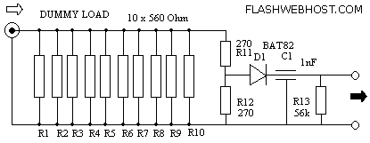
RF Dummy load
The load described here is capable of handling up to 10 watts of RF power for a couple of minutes and is designed for the widely used 50 ohms impedance. It consists of ten parallel connected 560 ohms 1 watt...
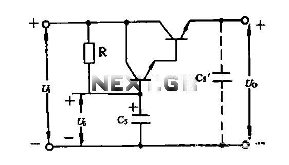
Electronic filter
An electronic filter is utilized to enhance the filtering effect of capacitor C5. Capacitors in this configuration form a composite circuit with the electronic filter, as illustrated in the accompanying figure. The advantage of using smaller capacitors (5 to 20...
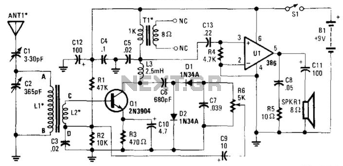
Reflex Radio Receiver
The RF signal is transmitted from the antenna through CI to a tuned circuit consisting of LI and C2. One end of L2 delivers the RF signal to the base of Q1 for amplification, while the other end connects to...
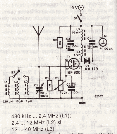
Radio Field Indicator Circuit
An RF field indicator is needed to verify power stages and transmitter antennas. This radio field indicator allows for the measurement of radiated energy from antennas.
An RF field indicator is a crucial device in the field of telecommunications and broadcasting....
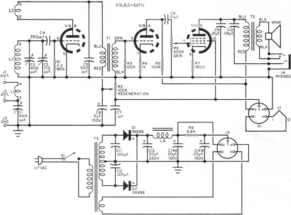
One Receiver
RF Cafe visitor David M. requested the scanning and posting of an article from the January 1963 edition of Popular Electronics, authored by Philip Hatfield from the Receiving Tube Department of General Electric. The article describes a straightforward design utilizing...
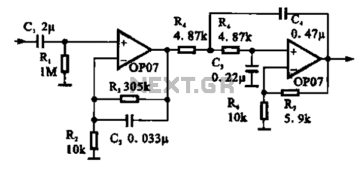
Broadband 0.1 to 10Hz filter amplifier
Broadband 0.1 to 10 Hz filter amplifier. The broadband circuit consists of two operational amplifiers configured as filter amplifiers operating in the frequency range of 0.1 to 10 Hz.
The broadband filter amplifier circuit utilizes two operational amplifiers (op-amps) to achieve...
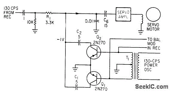
SYNCHRONOUS FILTER FOR ADF
Separates 130-cps motor drive voltage from voice frequencies in the output of an ADF receiver. P. V. Sparks, Servo Filter and Gain Control Improve Automatic Direction Finder, Electronics, 34:23, p 110-113.
The circuit described functions as a filter that effectively separates...
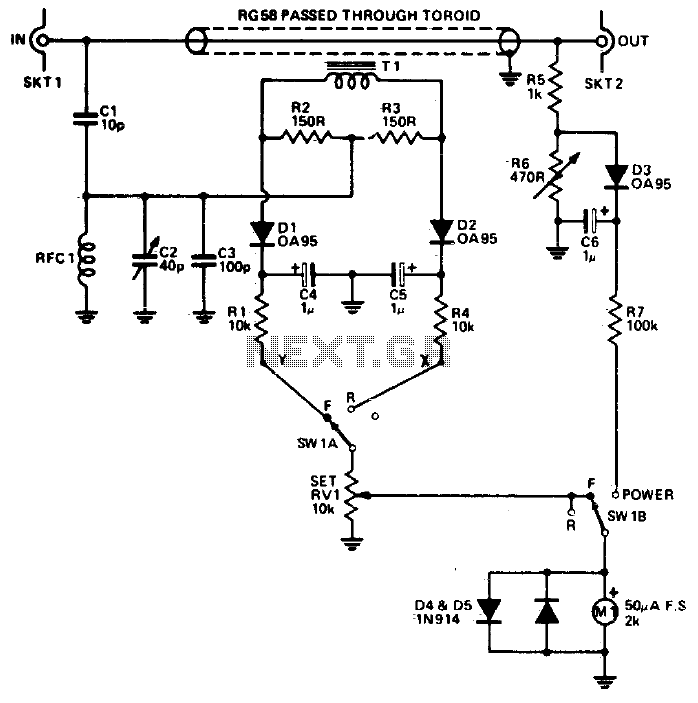
Rf power meter
The reflectometer (SWR power meter) operates across three decades, ranging from 100 kHz to 100 MHz. It can be designed to handle RF power levels as low as 500 mW and up to 500 watts.
The reflectometer, also known as a...
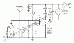
RF field strength meter circuit
A sensitive and reliable RF field strength meter is an invaluable instrument in amateur radio and in the radio-controlled model area. A field strength meter is.
A radio frequency (RF) field strength meter is a specialized device used to measure the...