


Radio Collar Transmitter Circuit
#NE555
#transmitter
#RF
#radio collar
#timer IC
#wireless
#animal tracking
#frequency modulation
#circuit design
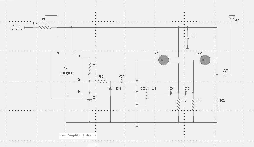
Description: The circuit diagram of the Radio Collar Transmitter is presented here. This circuit is based on the NE555 integrated circuit, which serves as the central component.
The Radio Collar Transmitter circuit utilizes the NE555 timer IC to generate a modulated signal suitable for transmission. The NE555 can be configured in astable mode to produce a continuous square wave output, which is essential for creating the radio frequency signal. This signal can then be amplified and transmitted via an antenna.
In the typical configuration, the NE555 is connected with resistors and capacitors that determine the frequency and duty cycle of the output waveform. The frequency is set by the values of the resistors (R1 and R2) and the capacitor (C1) connected to the timing pins of the NE555. The duty cycle can be adjusted by varying R1 and R2, allowing for flexibility in the modulation of the output signal.
The output from the NE555 is then fed into a radio frequency amplifier circuit, which may consist of a transistor or a dedicated RF amplifier IC. This stage boosts the signal strength to ensure that it can be effectively transmitted over a distance. The amplified signal is then connected to an antenna, which converts the electrical signals into radio waves.
Power supply considerations are also critical in the design of the Radio Collar Transmitter. Typically, a battery or a small power source is used to provide the necessary voltage and current for the circuit. Proper decoupling capacitors should be included to filter out noise and ensure stable operation of the NE555 timer.
Overall, the Radio Collar Transmitter circuit is a practical application of the NE555 timer IC, showcasing its versatility in generating modulated signals for wireless communication purposes. Proper layout and component selection are essential for optimizing the performance and range of the transmitter.The circuit diagram of Radio Collar Transmitter has been described here. This circuit is based on the IC NE 555 which is the central part.
The Radio Collar Transmitter circuit utilizes the NE555 timer IC to generate a modulated signal suitable for transmission. The NE555 can be configured in astable mode to produce a continuous square wave output, which is essential for creating the radio frequency signal. This signal can then be amplified and transmitted via an antenna.
In the typical configuration, the NE555 is connected with resistors and capacitors that determine the frequency and duty cycle of the output waveform. The frequency is set by the values of the resistors (R1 and R2) and the capacitor (C1) connected to the timing pins of the NE555. The duty cycle can be adjusted by varying R1 and R2, allowing for flexibility in the modulation of the output signal.
The output from the NE555 is then fed into a radio frequency amplifier circuit, which may consist of a transistor or a dedicated RF amplifier IC. This stage boosts the signal strength to ensure that it can be effectively transmitted over a distance. The amplified signal is then connected to an antenna, which converts the electrical signals into radio waves.
Power supply considerations are also critical in the design of the Radio Collar Transmitter. Typically, a battery or a small power source is used to provide the necessary voltage and current for the circuit. Proper decoupling capacitors should be included to filter out noise and ensure stable operation of the NE555 timer.
Overall, the Radio Collar Transmitter circuit is a practical application of the NE555 timer IC, showcasing its versatility in generating modulated signals for wireless communication purposes. Proper layout and component selection are essential for optimizing the performance and range of the transmitter.The circuit diagram of Radio Collar Transmitter has been described here. This circuit is based on the IC NE 555 which is the central part.
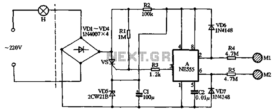
With NE555 make double touch light switch 2
The circuit illustrated in the figure features a dashed line on the left, representing a standard lighting circuit, while the right side is responsible for the dual functionality of touch activation using the NE555 timer. Components VD1 through VD4 form...
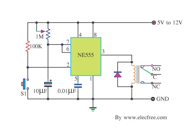
Basic Timer Control with NE555
Many friends take an interest in the circuit involving the highly popular IC 555, which is an integrated circuit. This circuit sets the time in a basic manner.
The IC 555 timer is a versatile and widely utilized component in electronics,...
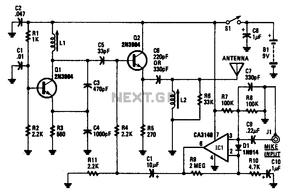
Wireless am microphone
The transistor Q1 and its associated components form a tunable RF oscillator. The RF signal is directed to transistor Q2, which functions as the modulator. Operational amplifier IC1 amplifies the audio signal and transmits it through resistor R4 to the...
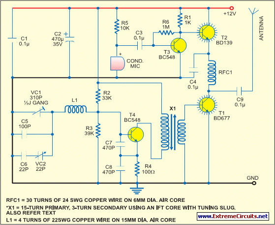
Simple Short-Wave Transmitter
This low-cost short-wave transmitter is tunable from 10 to 15 MHz using a ½J gang condenser VC1, which sets the carrier frequency in conjunction with inductor L1. Frequency trimming is achieved with VC2. The carrier signal is amplified by transistor...
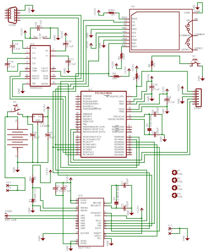
tx atv
This project was developed in collaboration with several other operators, particularly Marco IW1DGG, within a local radio club. The initial goal was to create a simple transmitter capable of providing sufficient power to excite the local ATV repeater. However, suitable...
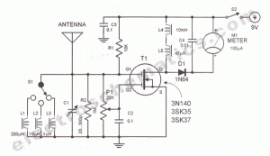
RF field strength meter circuit
A sensitive and reliable RF field strength meter is an invaluable instrument in amateur radio and in the radio-controlled model area. A field strength meter is.
A radio frequency (RF) field strength meter is a specialized device used to measure the...
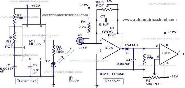
Moving Sensor / Detector Schematic Diagram using IC NE555 and Phototransistor L14F
All components used in the Moving Sensor/Detector Schematic Diagram utilize the IC NE555 and the Phototransistor L14F. The primary component in this circuit is the IC NE555, along with an IR LED, the Phototransistor L14F, and the IC LM1458. The...
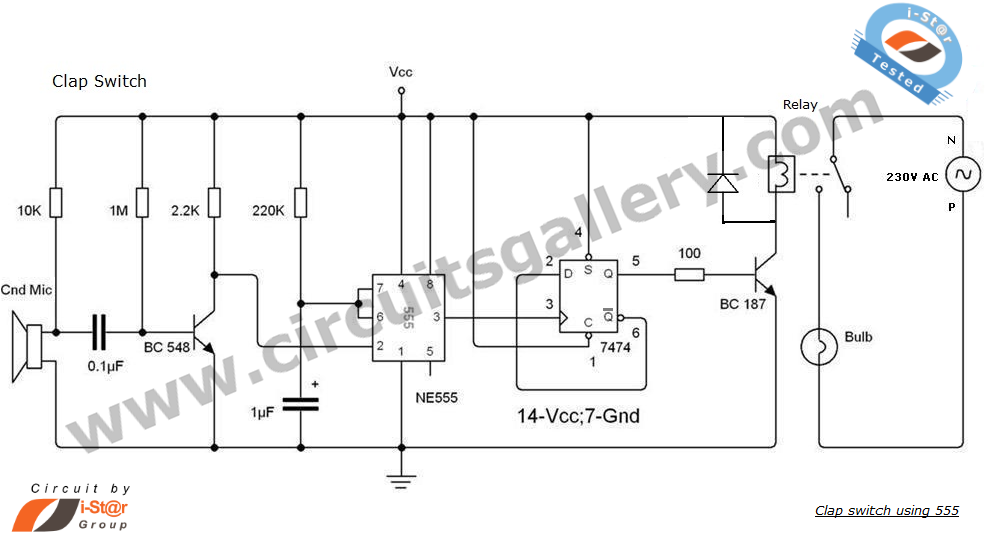
Clap Switch Circuit using NE555 timer IC
This is an intriguing 555 timer circuit designed to entertain and engage individuals while studying electronics in educational settings. Commonly referred to as a clap switch circuit, it operates as a sound-controlled flip-flop. This sound-controlled light can also function as...
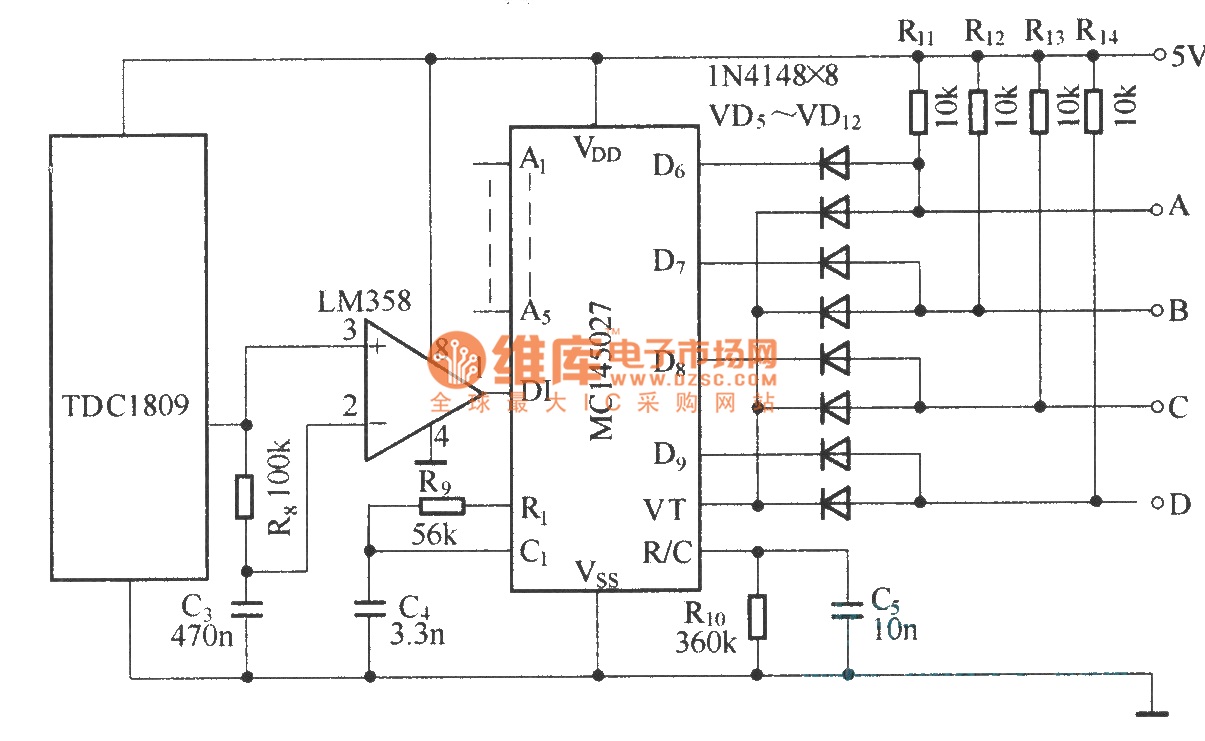
Composed of TDC1808/TDC1809 digital coding control circuit diagram
The TDC1808/TDC1809 is a pair of wireless remote control transmitter and receiver components. They utilize an internal antenna to transmit both digital and analog signals. These components are suitable for various wireless remote control devices. Key features include compact size,...