


RF power and VSWR meter
#RF power meter
#VSWR meter
#VHF
#UHF
#SWR-meter
#bridge circuit
#signal generator
#antenna testing
#N-connectors
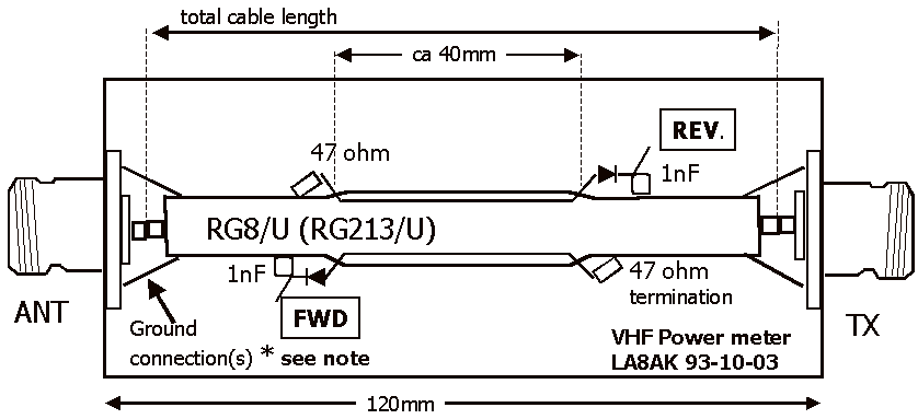
Description: The Inter-Power SWR-5 upper right isn't worth a penny. Got it from a mate to use with a beacon, but I burnt it out with only 3.5-4W morse signal on 70cm. Removed the bridge and installed my own pick-up line suggested by LA8OJ and now it is fb for VHF/UHF. The old Hansen, Reace or whatever make SWR-meter from 1968 from J. B. Lowe or later has a relatively good bridge, it works fb on 2m - provided careful operation, sensitivity is very good on 2m! It is easy to destroy, but works fb with level down to 10mW, have used it on 180-190MHz to test TV-receiver antennas using Wavetek Model 3001 signal generator, but mounted N-connectors to make it look sufficiently professional at work, see next note. More: The Inter-Power SWR5 was renovated and since the meter and box was so nice looking I decided to keep it and remove the useless bridge. Mounting wire is pulled under the braid for a length of 40mm. It is easier for the old type RG8/U, where the braid often is somewhat looser than for RG213/U. I wouldn't think about using RG214/U! It was some struggle to mount the bridge and solder in the right order since it is just as must space as you need. Another application of the same technique. It is so easy to build pick-up bridges, it is just fun. Here is my 2m line - permanently inserted between the PA to antenna. Suppose RG8/U type coax-cable is better than RG213/U since the braid may be somewhat loose, but must not be dark and corroded.
The Inter-Power SWR-5 is a standing wave ratio (SWR) meter designed for use in VHF and UHF applications. This device is used to measure the efficiency of an antenna system by determining the ratio of reflected power to transmitted power. The original design may have limitations, as indicated by the user's experience with burning out the device under low power conditions (3.5-4W) on the 70cm band.
After modifying the SWR-5, the user removed the original bridge and replaced it with a custom pick-up line, which significantly improved the performance for VHF/UHF applications. This modification is indicative of a common practice among amateur radio operators to enhance the functionality of existing equipment. The user also referenced the performance of older SWR meters, such as those from Hansen or Reace, which, despite their age, can provide reliable readings if handled carefully.
The mention of using a Wavetek Model 3001 signal generator for testing antennas illustrates the practical application of the SWR meter in evaluating antenna performance at specific frequencies, such as 180-190 MHz. The choice to use N-connectors for improved durability and professionalism further demonstrates the focus on quality in amateur radio setups.
The discussion of coaxial cables highlights the importance of selecting the right type for optimal performance. RG8/U is preferred over RG213/U due to its looser braid, which can facilitate better connections in certain setups, particularly in older equipment. The user also emphasizes the need for clean and corrosion-free connections to ensure accurate measurements and reliable operation.
Overall, the modifications and techniques described reflect a hands-on approach to enhancing the functionality of RF measurement tools, showcasing both creativity and technical knowledge in the field of amateur radio operation.The Inter-Power SWR-5 - upper right - "isn't worth a penny". Got it from a mate to use with a beacon, but I burnt it out with only 3.5-4W morse signal on 70cm. Removed the bridge and installed my own pick-up line (suggested by LA8OJ) and now it is fb for VHF/UHF. The old Hansen, Reace or whatever make "SWR-meter from 1968 (from J. B. Lowe) or later has a relatively good bridge, it works fb on 2m - provided careful operation, sensitivity is very good on 2m!
It is easy to destroy, but works fb with level down to 10mW, have used it on 180-190MHz to test TV-receiver antennas using Wavetek Model 3001 signal generator, but mounted N-connectors to make it look sufficient professional at work, see next note. The Inter-Power SWR5 was renovated and since the meter and box was so nice looking I decided to keep it and remove the useless bridge. Mounting wire is pulled under the braid for a length of 40mm. It is easier for the old type RG8/U, where the braid often is somewhat looser than for RG213/U. I wouldn't think about using RG214/U! It was some struggle to mount the bridge, and solder in the right order since it is just as must space as you need.
Another application of the same technique. It is so easy to build pick-up bridges, it is just fun. Here is my 2m line - permanently inserted between the PA to antenna. Suppose RG8/U type coax-cable is better than RG213/U since the braid may be somewhat loose, but must not be dark and corroded.
The Inter-Power SWR-5 is a standing wave ratio (SWR) meter designed for use in VHF and UHF applications. This device is used to measure the efficiency of an antenna system by determining the ratio of reflected power to transmitted power. The original design may have limitations, as indicated by the user's experience with burning out the device under low power conditions (3.5-4W) on the 70cm band.
After modifying the SWR-5, the user removed the original bridge and replaced it with a custom pick-up line, which significantly improved the performance for VHF/UHF applications. This modification is indicative of a common practice among amateur radio operators to enhance the functionality of existing equipment. The user also referenced the performance of older SWR meters, such as those from Hansen or Reace, which, despite their age, can provide reliable readings if handled carefully.
The mention of using a Wavetek Model 3001 signal generator for testing antennas illustrates the practical application of the SWR meter in evaluating antenna performance at specific frequencies, such as 180-190 MHz. The choice to use N-connectors for improved durability and professionalism further demonstrates the focus on quality in amateur radio setups.
The discussion of coaxial cables highlights the importance of selecting the right type for optimal performance. RG8/U is preferred over RG213/U due to its looser braid, which can facilitate better connections in certain setups, particularly in older equipment. The user also emphasizes the need for clean and corrosion-free connections to ensure accurate measurements and reliable operation.
Overall, the modifications and techniques described reflect a hands-on approach to enhancing the functionality of RF measurement tools, showcasing both creativity and technical knowledge in the field of amateur radio operation.The Inter-Power SWR-5 - upper right - "isn't worth a penny". Got it from a mate to use with a beacon, but I burnt it out with only 3.5-4W morse signal on 70cm. Removed the bridge and installed my own pick-up line (suggested by LA8OJ) and now it is fb for VHF/UHF. The old Hansen, Reace or whatever make "SWR-meter from 1968 (from J. B. Lowe) or later has a relatively good bridge, it works fb on 2m - provided careful operation, sensitivity is very good on 2m!
It is easy to destroy, but works fb with level down to 10mW, have used it on 180-190MHz to test TV-receiver antennas using Wavetek Model 3001 signal generator, but mounted N-connectors to make it look sufficient professional at work, see next note. The Inter-Power SWR5 was renovated and since the meter and box was so nice looking I decided to keep it and remove the useless bridge. Mounting wire is pulled under the braid for a length of 40mm. It is easier for the old type RG8/U, where the braid often is somewhat looser than for RG213/U. I wouldn't think about using RG214/U! It was some struggle to mount the bridge, and solder in the right order since it is just as must space as you need.
Another application of the same technique. It is so easy to build pick-up bridges, it is just fun. Here is my 2m line - permanently inserted between the PA to antenna. Suppose RG8/U type coax-cable is better than RG213/U since the braid may be somewhat loose, but must not be dark and corroded.
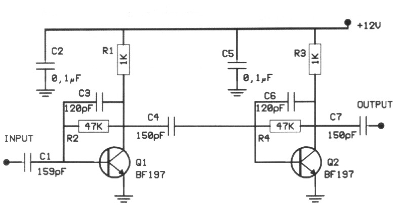
VHF TV Signal Amplifier
Many times we needed to strengthen a small signal in the region of VHF or FM. The preamplifier that we propose offers 20dB in all the region of VHF and it still can reach also their 500MHz. The amplifier is...
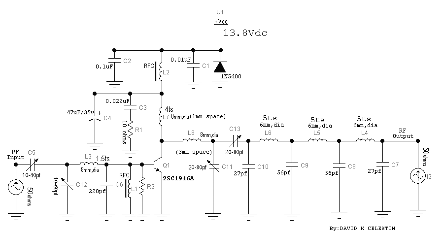
VHF Amplifier with 30 Watts Power
The circuit was designed to increase an input signal of 4 Watts to 6 Watts, operating within the VHF radio frequency band, specifically for FM transmission.
This circuit is engineered to amplify radio frequency signals in the VHF band, which typically...
BF494 Transistor For UHF Indicator Wavemeter
The following circuit illustrates a UHF Indicator Wavemeter Circuit Diagram. This circuit utilizes dual BF494 transistors. Features: the oscillator is...
The UHF Indicator Wavemeter Circuit is designed to measure and indicate the frequency of ultra-high frequency (UHF) signals. The circuit primarily...
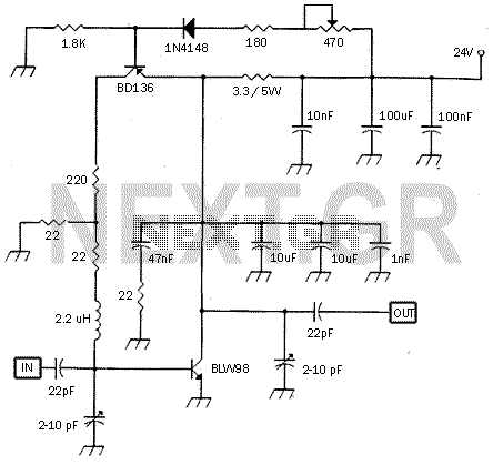
5 Watt UHF TV Linear amplifier
This small circuit is a linear amplifier for driving small UHF TV transmitters. Its gain is 7 dB and can amplify a signal between 450-800 MHz. You can drive the circuit with 1 to 1.5 Watts signal. Better use double...
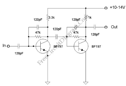
VHF-UHF Antenna Amplifier (Booster) 40-500MHz
This amplifier has VHF (very high frequency) and UHF (ultra high frequency) response, and it can be used as a receiver booster, for example. Here is the schematic.
The described amplifier is designed to enhance signal reception in the VHF and...
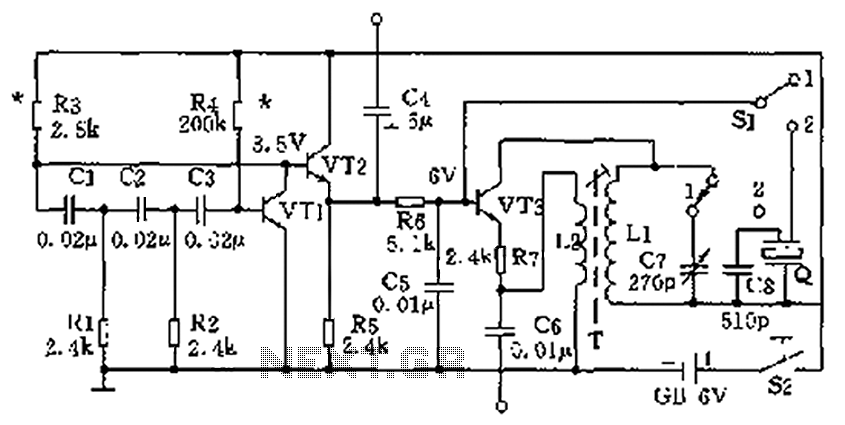
High and low frequency signal generator circuit diagram
The high-frequency signal generator is designed to produce a low frequency of 1 kHz, an intermediate frequency (IF) signal of 465 kHz, and high frequencies ranging from 525 kHz to 1605 kHz. This device is particularly useful for radio repair...
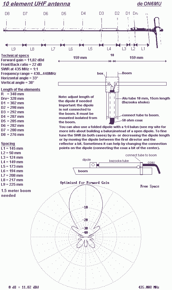
Optimized 10-element UHF Yagi Antenna
The elements diameter of the antenna may vary between 5...8mm and the dipole diameter may vary between 8...12mm (12mm recommended) without the need of changing anything to the length or spacing. All elements except the dipole are electrically connected to...
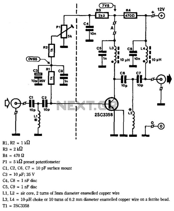
Uhf Tv-Line Amplifier
This circuit provides a gain of 10 to 15 dB from 400 to 850 MHz, making it particularly effective in scenarios where the television signal is weak. Additionally, the filters can be customized to meet individual user requirements. Construction is...
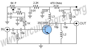
uhf antenna amplifier booster
This UHF antenna amplifier circuit, also referred to as a UHF antenna booster circuit, is designed to amplify signals within the UHF band, specifically from 400 MHz to 850 MHz. The circuit employs a single transistor and provides an amplification...