


Schematic Diagram BA1404 Stereo transmitter circuit
#BA1404
#stereo transmitter
#FM modulator
#RF amplifier
#composite signals
#stereo modulator
#wireless transmission
#audio broadcasting
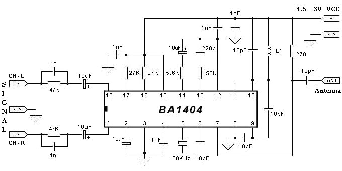
Description: The BA1404 FM stereo modulator IC includes all the necessary components to design a simple, high-efficiency stereo transmitter circuit. It features a stereo modulator that generates composite stereo signals, an FM modulator for creating FM signals, and an RF amplifier. The FM stereo transmitter produces composite signals composed of a main (L+R) signal, a sub (L-R) signal, and a pilot (19 kHz) signal using a 38 kHz crystal oscillator. This FM stereo transmitter circuit requires a DC power supply capable of providing an output voltage between 1.5 and 3 volts. This circuit project can be utilized for FM stereo transmitters or wireless microphone applications.
The BA1404 IC is a versatile component designed for audio transmission applications, allowing for the efficient modulation of audio signals into FM signals suitable for broadcast. The stereo modulator within the IC combines left and right audio channels into a composite signal. The main signal, which is the sum of the left and right channels (L+R), carries the primary audio content, while the sub signal (L-R) provides the differential information between the two channels, enabling stereo sound reproduction.
The pilot signal at 19 kHz serves as a synchronization reference for FM receivers, ensuring that the stereo separation is accurately decoded. The use of a 38 kHz crystal oscillator is critical for generating the necessary frequencies for modulation, ensuring stability and clarity in the transmitted audio.
For operation, a DC power supply providing between 1.5 and 3 volts is required. This allows the circuit to function efficiently while minimizing power consumption, making it suitable for portable applications. The design can be implemented in various applications, including FM stereo transmitters for broadcasting audio content over short distances and wireless microphones, where clear audio transmission is essential.
In summary, the BA1404 FM stereo modulator IC is an effective solution for creating compact and efficient stereo transmission systems, combining simplicity in design with high-performance audio modulation capabilities.The BA1404 fm stereo modulator Ic contains all parts needed to design an simple high efficiency stereo transmitter circuit, it contains a stereo modulator that creates stereo composites signals, an FM modulator that creates FM signals and a RF amplifier. The fm stereo transmitter develops composite signals made up of a main(L+R) signal and sub(L- R) signal and a pilot (19KHz) signal using a 38KHz crystal oscillators. For this FM stereo transmitter circuit you`ll need a DC power supply that can provide an output voltage between 1. 5 an 3 volts. This fm stereo transmitter circuit project can be used for FM stereo transmitters or wireless microphone circuits.
The BA1404 IC is a versatile component designed for audio transmission applications, allowing for the efficient modulation of audio signals into FM signals suitable for broadcast. The stereo modulator within the IC combines left and right audio channels into a composite signal. The main signal, which is the sum of the left and right channels (L+R), carries the primary audio content, while the sub signal (L-R) provides the differential information between the two channels, enabling stereo sound reproduction.
The pilot signal at 19 kHz serves as a synchronization reference for FM receivers, ensuring that the stereo separation is accurately decoded. The use of a 38 kHz crystal oscillator is critical for generating the necessary frequencies for modulation, ensuring stability and clarity in the transmitted audio.
For operation, a DC power supply providing between 1.5 and 3 volts is required. This allows the circuit to function efficiently while minimizing power consumption, making it suitable for portable applications. The design can be implemented in various applications, including FM stereo transmitters for broadcasting audio content over short distances and wireless microphones, where clear audio transmission is essential.
In summary, the BA1404 FM stereo modulator IC is an effective solution for creating compact and efficient stereo transmission systems, combining simplicity in design with high-performance audio modulation capabilities.The BA1404 fm stereo modulator Ic contains all parts needed to design an simple high efficiency stereo transmitter circuit, it contains a stereo modulator that creates stereo composites signals, an FM modulator that creates FM signals and a RF amplifier. The fm stereo transmitter develops composite signals made up of a main(L+R) signal and sub(L- R) signal and a pilot (19KHz) signal using a 38KHz crystal oscillators. For this FM stereo transmitter circuit you`ll need a DC power supply that can provide an output voltage between 1. 5 an 3 volts. This fm stereo transmitter circuit project can be used for FM stereo transmitters or wireless microphone circuits.

10 watt rf amplifier for 18mhz by
This project aims to provide a 0.55-watt input that can easily be amplified to a 10-watt output. The two linear amplifiers are designed for use with QRP SSB/CW/FM/AM transmitters on the amateur bands of 15 and 17 meters and can...

5W 7Mhz Rf Power Amplifier Circuit
The circuit illustrated is designed to generate up to 5 watts of RF output in the 40-meter (7 MHz) amateur band. The coils depicted are wound on toroidal cores from Armdon Associates Inc., with part numbers provided in the schematic....

135-175Mhz amplifier
Cl. C2 ARCO #462, 2 to 60 pF, trimmer capacitors Li, 3 turns of #20 AWG wire on 1/4" diameter L2, β turns of #20 AWG on 1/4" diameter Ti. Additionally, there is 1 turn of 25 Ω coax on...

2W RF Amplifier with MOSFET LF2810A
This is a 2W RF amplifier circuit built with the power MOSFET LF2810A. The schematic of the microstrip single-stage RF amplifier is shown in Figure A. The amplifier utilizes the M/A-Com LF2810A MOSFET, which is rated for a power output...

Wideband Rf Amplifier
This RF amplifier features a wide bandwidth and dynamic range. It provides a gain of 10 dB, with a noise figure of less than 5 dB. The third-order intercept point (IP3) is -40 dB at an output of +22 dBm...
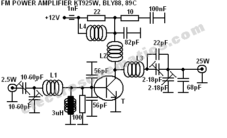
300W FM RF Amplifier Circuit
This 300W RF power amplifier for an FM transmitter utilizes 2 x TP9383 transistors. It operates within the 88 - 108 MHz frequency band.
The 300W RF power amplifier is designed specifically for FM transmission applications, providing high power output suitable...

4 watt 900mhz rf amplifier
This RF amplifier circuit delivers a power output of 4 Watts at a frequency of 900 MHz. It utilizes Wilkinson power dividers in the base and collector circuits of transistors Q2 and Q3. Two SD1853 driver application transistors are paralleled...
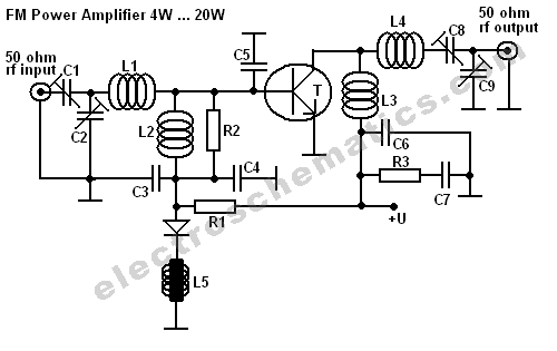
BLY94 50W RF Amplifier Circuit
This FM RF power amplifier circuit is constructed using a BLY94 transistor, which can deliver up to 50W at a frequency of 175MHz with a power gain of 7dB, resulting in approximately 5 times power amplification. However, in this schematic,...
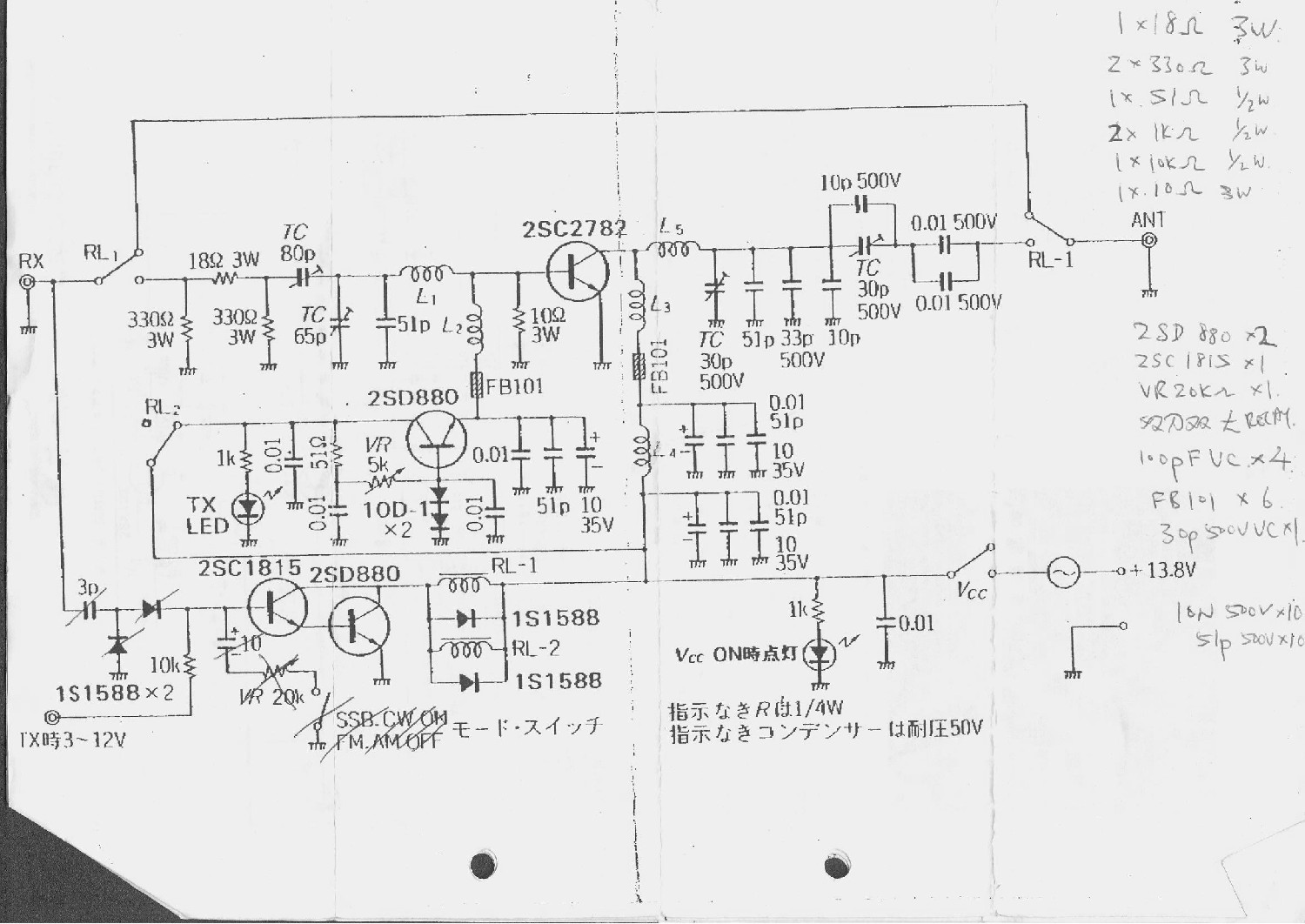
100W Transmitter RF Power Amplifier 2SC2782
This is a 6-meter band transmitter RF power amplifier (50 MHz) with a 100W output. It is compatible with the FT-736R and is driven by a 10W signal for 6m SSB DX. The construction information is sourced from Japan CQ...