


Schematics VHF FM Receiver TDA7000 88-108 MHz
#VHF
#FM receiver
#TDA7000
#88-108 MHz
#squelch
#crystal earphone
#high impedance headphones
#output capacitor
#adjustable squelch
#radio circuit

Description: The 10K resistor is necessary if the receiver is to mute (squelch) under no-signal conditions. An additional 100K resistor can be added in series with this resistor to create an adjustable squelch. This circuit is designed to drive a crystal earphone or high-impedance headphones directly; however, an output isolating capacitor (100nF) is required for connecting to other devices. The inductor L1 consists of 6 turns of No 18 SWG enamelled wire wound on a 5mm former, although adjustments to the values may be needed. A coil fabricated on the PCB itself was used and tuned with a trimmer capacitor. This receiver is very sensitive, compact, and performs exceptionally well. It is a complete superheterodyne receiver featuring a very low RC-tuned intermediate frequency (IF). The action of the Automatic Frequency Control (AFC) effectively rejects the image signal. With appropriate antennas and terrain, this receiver can achieve a range of up to 500 meters from the FM wireless microphone v5. The receiver is available as a kit, which includes solder, antenna wire, and all necessary components. Users will only need to provide a battery, tools, and a soldering iron. A fully assembled kit version is also available.
The described circuit features a superheterodyne receiver design, which is known for its ability to provide excellent sensitivity and selectivity in radio frequency applications. The use of a 10K resistor for squelching is a standard approach in RF receiver design, allowing the circuit to mute audio output when no signal is detected, thus reducing noise and enhancing user experience. The optional 100K resistor in series enables the user to adjust the squelch threshold, providing flexibility based on environmental conditions and signal strength.
The inductor L1, constructed from No 18 SWG enamelled wire, is a critical component in determining the resonant frequency of the circuit. The choice of a 5mm former for winding the coil aids in achieving the desired inductance while maintaining a compact form factor. The tuning process using a trimmer capacitor allows for fine adjustments to the circuit's frequency response, which is essential for optimizing performance and ensuring reliable operation across varying conditions.
The output isolating capacitor (100nF) serves a dual purpose: it blocks any DC component that may be present in the output signal and allows only the AC audio signal to pass through to the connected device. This is particularly important when interfacing with devices that may be sensitive to DC levels, such as audio amplifiers or speakers.
The AFC circuit incorporated within the receiver plays a vital role in maintaining stable reception by automatically adjusting the tuning to compensate for frequency drift, which can occur due to temperature variations or other environmental factors. This feature enhances the receiver's ability to reject unwanted image frequencies, allowing for clearer audio output.
Overall, the kit format provides an accessible way for enthusiasts to build their own high-performance receiver, with the added benefit of including all necessary components and tools. The option for a fully assembled version caters to users who prefer immediate functionality without the need for assembly. This receiver kit not only demonstrates practical electronics principles but also offers a rewarding experience for those interested in radio technology.The 10K resistor (*) is only required if you want the receiver to mute (squelch) under no-signal conditions. You could add a 100K in series with this resistor to get an adjustable squelch. This circuit will JUST drive a crystal earphone or high impedance headphones directly, but an output isolating capacitor (100nF) is needed for any other device.
L1 is 6 turns No 18 SWG enamelled wire on a 5mm former, but you may have to play with the values a bit. I used a coil fabricated on the PCB itself, tuned with a trimmer capacitor. As you can see, this receiver is VERY sensitive, small and seems to work very well indeed. It is in fact a full superhet receiver with a very low RC tuned IF. The Image signal is rejected by the action of the AFC which functions to push it away. With suitable antennas and terrain, with this receiver you could easily get the full 500 meters from the FM wireless microphone v5.
I am offering this receiver in kit form, including solder, antenna wire etc. All you will need to provide is the battery, tools and soldering iron. Here is the kit version fully assembled.
The described circuit features a superheterodyne receiver design, which is known for its ability to provide excellent sensitivity and selectivity in radio frequency applications. The use of a 10K resistor for squelching is a standard approach in RF receiver design, allowing the circuit to mute audio output when no signal is detected, thus reducing noise and enhancing user experience. The optional 100K resistor in series enables the user to adjust the squelch threshold, providing flexibility based on environmental conditions and signal strength.
The inductor L1, constructed from No 18 SWG enamelled wire, is a critical component in determining the resonant frequency of the circuit. The choice of a 5mm former for winding the coil aids in achieving the desired inductance while maintaining a compact form factor. The tuning process using a trimmer capacitor allows for fine adjustments to the circuit's frequency response, which is essential for optimizing performance and ensuring reliable operation across varying conditions.
The output isolating capacitor (100nF) serves a dual purpose: it blocks any DC component that may be present in the output signal and allows only the AC audio signal to pass through to the connected device. This is particularly important when interfacing with devices that may be sensitive to DC levels, such as audio amplifiers or speakers.
The AFC circuit incorporated within the receiver plays a vital role in maintaining stable reception by automatically adjusting the tuning to compensate for frequency drift, which can occur due to temperature variations or other environmental factors. This feature enhances the receiver's ability to reject unwanted image frequencies, allowing for clearer audio output.
Overall, the kit format provides an accessible way for enthusiasts to build their own high-performance receiver, with the added benefit of including all necessary components and tools. The option for a fully assembled version caters to users who prefer immediate functionality without the need for assembly. This receiver kit not only demonstrates practical electronics principles but also offers a rewarding experience for those interested in radio technology.The 10K resistor (*) is only required if you want the receiver to mute (squelch) under no-signal conditions. You could add a 100K in series with this resistor to get an adjustable squelch. This circuit will JUST drive a crystal earphone or high impedance headphones directly, but an output isolating capacitor (100nF) is needed for any other device.
L1 is 6 turns No 18 SWG enamelled wire on a 5mm former, but you may have to play with the values a bit. I used a coil fabricated on the PCB itself, tuned with a trimmer capacitor. As you can see, this receiver is VERY sensitive, small and seems to work very well indeed. It is in fact a full superhet receiver with a very low RC tuned IF. The Image signal is rejected by the action of the AFC which functions to push it away. With suitable antennas and terrain, with this receiver you could easily get the full 500 meters from the FM wireless microphone v5.
I am offering this receiver in kit form, including solder, antenna wire etc. All you will need to provide is the battery, tools and soldering iron. Here is the kit version fully assembled.
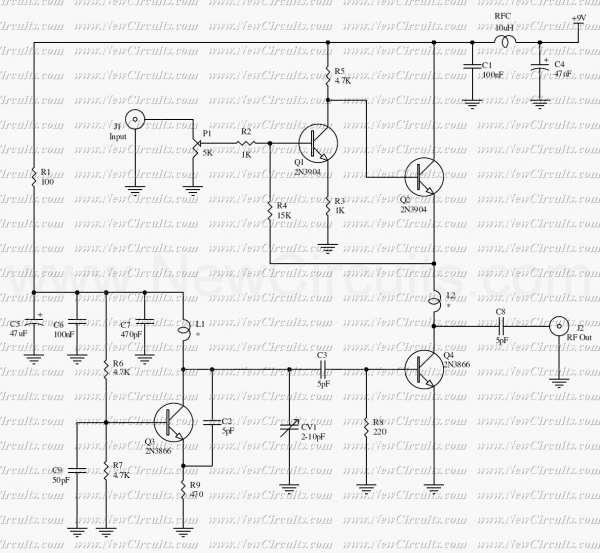
VHF Video Sender/Transmitter
This circuit is a powerful video sender in VHF band. The modulator section is designed to operate on either channels 7 to 13 or 14 to 29. For channels 7 to 13, L1 and L2 are 3 turns of #22...
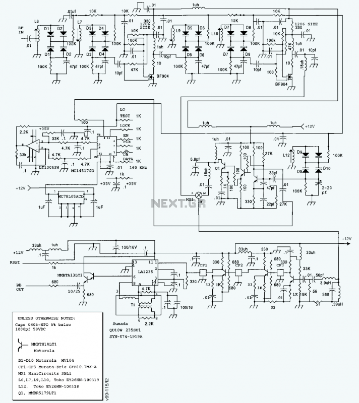
A high-performance FM receiver for audio and digital applicatons
A block diagram and a schematic of the receiver are shown in Figures 2 and 3, respectively. In Figure 3, L6 and L7 are spaced 0.6 inch for a loss of about 0.5 dB. Q4 is the first RF amplifier....
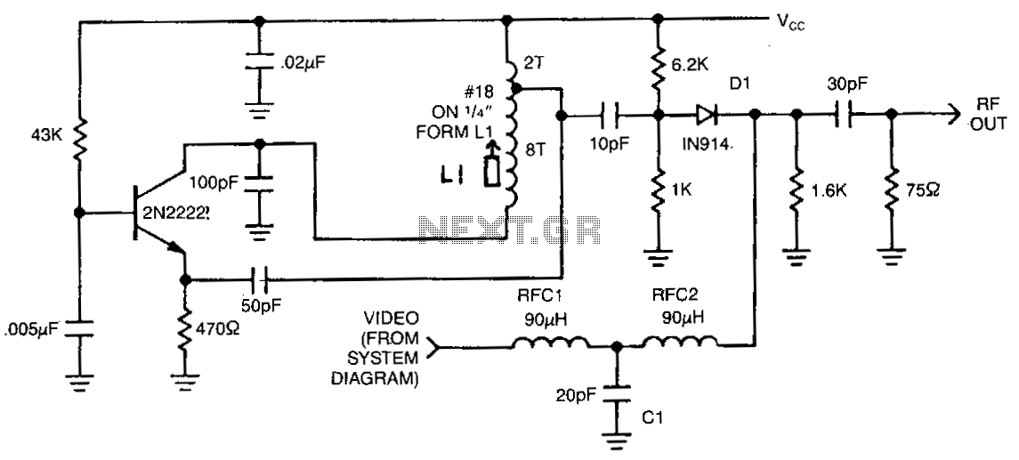
Vhf-modulator
This circuit utilizes an oscillator (2N2222) and a diode (D1) as a nonlinear mixer. The frequency is determined by a slug in inductor (L1). Additionally, RFCl, C1, and RFC2 create a low-pass filter that allows video signals to pass while...
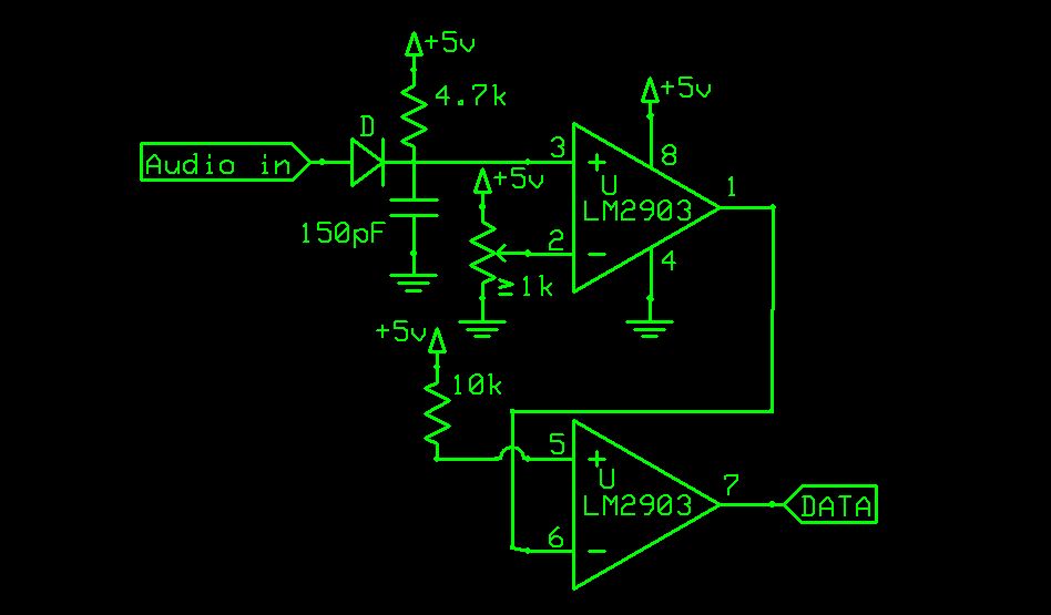
FM Data Receiver Module for Micro-controllers
There is a vast array of TX and RX modules available for microcontrollers. The least expensive option identified was priced at $9.99, which is reasonable, although there are memories of encountering FM receiver modules in the past.
The TX (transmitter) and...

FM reciever with classic TDA7000
With the P1 we regulate the intensity of sound. With the P2 we regulate the frequency of reception. Optionally: If you want to check the frequency with your PC it will be supposed you make the following energies: You assemble...
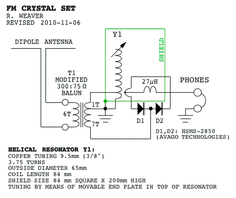
VHF FM Crstal Set Radios
Phase-sensitive detectors typically measure the difference between an input frequency-modulated (FM) signal and the same signal after it has been processed through a resonant circuit or a delay line. A 1N34 diode is suitable for detecting signals at 100 MHz,...
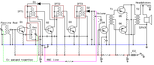
fm receiver basics
FM receivers are primarily of the superheterodyne type. To understand FM radio receivers, it is essential to consider the key differences between AM and FM signals. While it may seem obvious, these differences are significant. An AM receiver depends on...
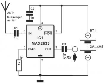
vhf rf preamp 100 175 mhz with max2633
This diagram represents a VHF RF preamplifier circuit operating within the frequency range of 100-175 MHz using a single MAX2633 chip. The circuit is suitable for the entire VHF broadcast and PMR band (100-175 MHz) and can be constructed easily...
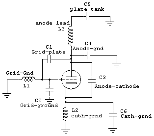
VHF Stability
The intelligent discussion of VHF systems necessitates an understanding of how VHF energy propagates through a system. At VHF frequencies, the wavelength is relatively short, calculated as F/983, where F is the frequency in MHz. For example, a typical 150...