


Sensitive frequency demodulator LM565 LM111
#frequency demodulator
#LM565
#LM111
#phase-locked loop
#wide frequency range
#sensitive circuit
#IC
#tracking
#demodulation
#RF
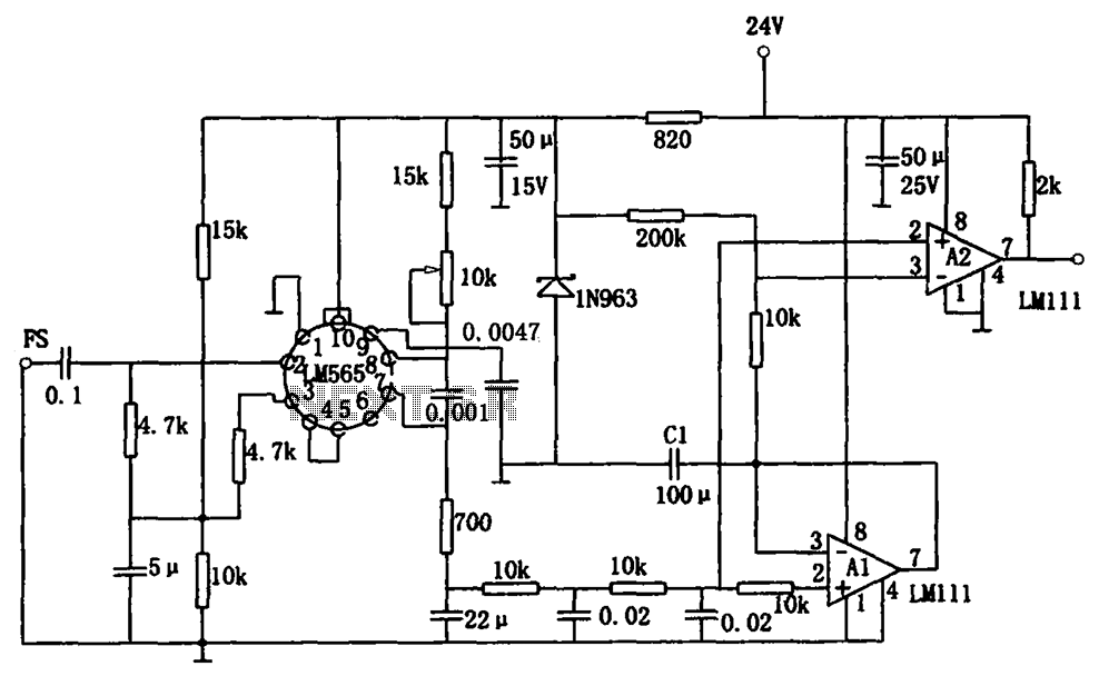
Description: The sensitive frequency demodulation circuit utilizes the LM565 integrated circuit in a phase-locked configuration, allowing it to track frequency offsets across a wide range. However, at small frequency offsets, the signal can produce a minimal demodulated output, causing the voltage-controlled oscillator to drift. This drift leads to an operating point shift in the comparator, resulting in errors. To address these issues, the circuit incorporates a DC regeneration section that enables stable operation even with small deviation signals. The demodulation circuit is fundamentally similar to general frequency demodulation circuits using the LM565 and the LM111 comparator. The key distinction lies in the A2 pin input signal, which is sourced from the peak hold circuit at A1 rather than directly from the LM565. During the FM input signal interval, the output from A1 is low, allowing capacitor C1 to discharge through A1's low output impedance and maintain the peak hold signal. This regenerative approach effectively compensates for voltage-controlled oscillator drift, ensuring that the output from the peak hold circuit remains trackable, thus allowing the comparator to function correctly.
The sensitive frequency demodulation circuit is designed to provide reliable performance even in challenging conditions where frequency offsets are minimal. The use of the LM565 IC in a phase-locked loop configuration enables the circuit to lock onto the input frequency and track variations effectively. The addition of the DC regeneration section is crucial for maintaining the integrity of the demodulated signal, especially when the output signal is weak.
In this circuit, the LM111 comparator plays a vital role in comparing the demodulated output signal against a reference voltage to determine the presence of frequency deviations. The unique configuration where the input to pin A2 is derived from the peak hold circuit at A1 allows for improved stability. This design ensures that even when the output signal from the demodulator is low, the capacitor C1 can discharge effectively, maintaining a consistent voltage level that the comparator can use for accurate frequency detection.
The peak hold circuit is essential for capturing the maximum value of the demodulated signal during the modulation interval, which is then used to inform the comparator of the signal state. The low output impedance of A1 ensures that the peak hold circuit can quickly respond to changes in the input signal, thus enhancing the overall responsiveness of the demodulation circuit.
In summary, the sensitive frequency demodulation circuit with LM565 and LM111 components is engineered to deliver precise frequency tracking capabilities while mitigating the effects of signal drift and ensuring stable operation under varying input conditions. This robustness makes it suitable for applications requiring high fidelity in frequency demodulation, such as communication systems and signal processing tasks. As shown for the sensitive frequency demodulation circuit. The circuit uses IC LM565 phase-locked configuration, can track the frequency offset over a wide frequency range. How ever, at small offsets the signal, due to the small demodulated output signal, the voltage controlled oscillator will drift a drift of the operating point of the comparator generates an error. This circuit is to overcome the above drawbacks, the circuit plus a DC regeneration section, which can stably work for a small deviation signal.
FIG, the demodulation circuit and general frequency demodulation circuit LM565 and LM111 comparator constituted substantially the same. The difference is that this circuit A2 pin input signal is not removed from the LM565 feet, but was removed from the peak hold circuit A1.
During the interval of the FM input signal, the output of A1 is low, thus holding the capacitor C1 is discharged A1 low output impedance, and the peak hold signal. With this direct approach to regeneration, despite the presence of a voltage controlled oscillator drift, but the peak hold circuit output can be tracked, so that the comparator can work.
The sensitive frequency demodulation circuit is designed to provide reliable performance even in challenging conditions where frequency offsets are minimal. The use of the LM565 IC in a phase-locked loop configuration enables the circuit to lock onto the input frequency and track variations effectively. The addition of the DC regeneration section is crucial for maintaining the integrity of the demodulated signal, especially when the output signal is weak.
In this circuit, the LM111 comparator plays a vital role in comparing the demodulated output signal against a reference voltage to determine the presence of frequency deviations. The unique configuration where the input to pin A2 is derived from the peak hold circuit at A1 allows for improved stability. This design ensures that even when the output signal from the demodulator is low, the capacitor C1 can discharge effectively, maintaining a consistent voltage level that the comparator can use for accurate frequency detection.
The peak hold circuit is essential for capturing the maximum value of the demodulated signal during the modulation interval, which is then used to inform the comparator of the signal state. The low output impedance of A1 ensures that the peak hold circuit can quickly respond to changes in the input signal, thus enhancing the overall responsiveness of the demodulation circuit.
In summary, the sensitive frequency demodulation circuit with LM565 and LM111 components is engineered to deliver precise frequency tracking capabilities while mitigating the effects of signal drift and ensuring stable operation under varying input conditions. This robustness makes it suitable for applications requiring high fidelity in frequency demodulation, such as communication systems and signal processing tasks. As shown for the sensitive frequency demodulation circuit. The circuit uses IC LM565 phase-locked configuration, can track the frequency offset over a wide frequency range. How ever, at small offsets the signal, due to the small demodulated output signal, the voltage controlled oscillator will drift a drift of the operating point of the comparator generates an error. This circuit is to overcome the above drawbacks, the circuit plus a DC regeneration section, which can stably work for a small deviation signal.
FIG, the demodulation circuit and general frequency demodulation circuit LM565 and LM111 comparator constituted substantially the same. The difference is that this circuit A2 pin input signal is not removed from the LM565 feet, but was removed from the peak hold circuit A1.
During the interval of the FM input signal, the output of A1 is low, thus holding the capacitor C1 is discharged A1 low output impedance, and the peak hold signal. With this direct approach to regeneration, despite the presence of a voltage controlled oscillator drift, but the peak hold circuit output can be tracked, so that the comparator can work.
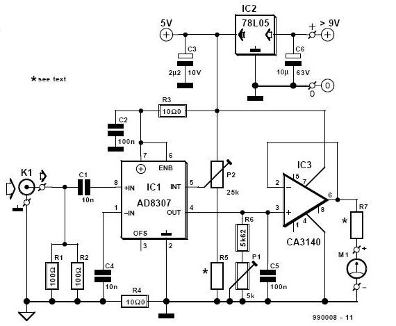
RF Decibel Meter Circuit
A DIY RF decibel (or power) meter is an essential instrument in any radio workshop. However, accurate, wideband models can be quite costly.
A DIY RF decibel meter serves as a valuable tool for measuring the power levels of radio frequency...
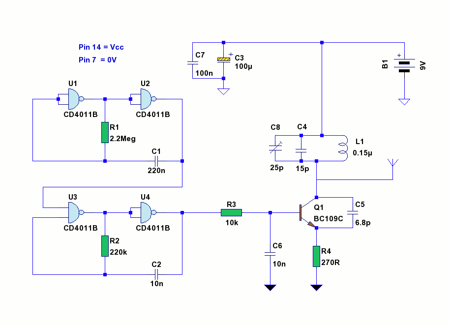
Tracking Transmitter
This is a small battery-operated tracking transmitter that broadcasts a repeating radio signal detectable by a directional antenna. The transmitter emits an isotropic signal across the FM band, specifically between 87 to 108 MHz. An ordinary FM radio can be...
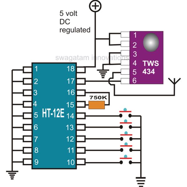
rf remote control encoder and decoder
This document explains two RF 433kHz remote control chips specifically designed for remote control applications. The IC TWS-434, along with its encoder chip HT-12E from Holtek, forms a high-quality transmitter circuit, while the chip RWS-434, paired with the decoder IC...
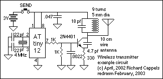
RF data link and remote control
This section describes an experimental low power, low bandwidth data signaling system that was initially made to operate at 55 MHz (television channel 2 in the U.S.). Before operating a radio transmitter, find out what kind of transmitter operation, if...
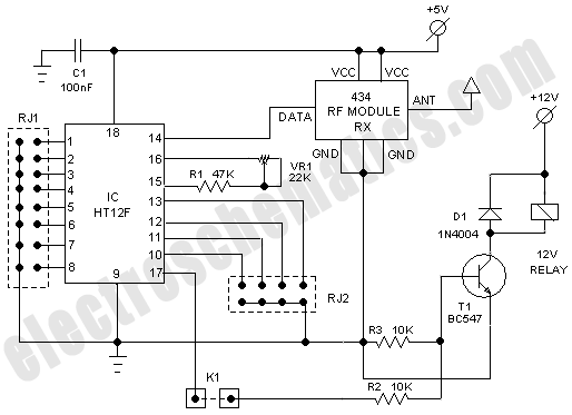
RF Based Wireless Remote Control Switch
It is often necessary to control electrical appliances remotely, even when there is no direct line of sight between the transmitter and receiver.
In modern electronic applications, remote control systems are increasingly utilized for various purposes, including home automation, industrial control,...
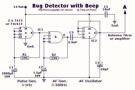
RF Bug detector
This circuit is not open for discussion. Although working perfectly, it was experimental. I will answer no emails in regards to this circuit. If you are looking for a more serious and reliable bug detector, go to the Countersurveillance Monitor...
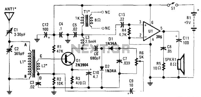
Reflex Radio Receiver
The RF signal is transmitted from the antenna through CI to a tuned circuit consisting of LI and C2. One end of L2 delivers the RF signal to the base of Q1 for amplification, while the other end connects to...
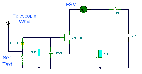
Field Strength Meter
This circuit is a wideband signal strength meter designed to respond to small variations in RF energy within the VHF spectrum. It is capable of detecting AM or FM modulation as well as a simple carrier wave. The circuit measures...
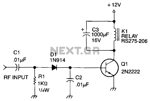
Rf-actuated-relay
Automatic antenna switching or RF power indication can be achieved with this circuit. Relay will key with less than 150 mW drive on 2 m.
The circuit designed for automatic antenna switching or RF power indication utilizes a relay that is...