


Shortwave Monitor
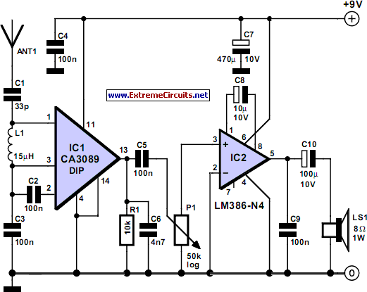
Description: This broadband AM receiver allows monitoring of the shortwave radio band. The circuit is intentionally designed for low selectivity and exhibits maximum sensitivity in the frequency range of 6 to 20 MHz, which encompasses most shortwave broadcast stations. In this setup, the station with the strongest signal is the easiest to receive. Notably, the signal strength of stations within this band fluctuates significantly due to the ionosphere's ability to reflect radio signals. This atmospheric layer is in constant motion, resulting in continuous variations in received signal strengths from different directions. During prototype testing, stations such as Radio Netherlands World Service, Radio Finland, and Deutsche Welle alternated as the strongest signals at regular intervals. This receiver not only provides an excellent indication of the numerous stations available in the shortwave band but also serves as a valuable tool for monitoring the ionosphere's condition. The circuit primarily consists of an RF amplifier and an AF amplifier. High-frequency amplification is achieved through the IF stage of a CA3089 integrated circuit (IC), which is typically used in FM receivers; however, the FM section is not utilized in this application. The internal level detector generates a signal strong enough to drive an audio amplifier directly. An LM386 IC is employed for this purpose, capable of directly driving an 8-ohm loudspeaker or headphones without difficulty. The power supply voltage is set at 9 V, and due to the low power consumption, a 9-V battery is suitable. Additionally, the circuit can operate down to approximately 5.5 V, extending battery life. The antenna requires some experimentation; reasonable results were achieved using a 50 cm length of wire, while a wire length between 5 to 15 meters is expected to yield even better performance at these frequencies.
This broadband AM receiver circuit is designed to effectively capture and amplify shortwave radio signals, making it an ideal tool for enthusiasts and researchers interested in radio communications and ionospheric conditions. The selection of the CA3089 IC for high-frequency amplification allows for efficient signal processing, as it is engineered to handle varying signal strengths and provide a clear audio output. The LM386 audio amplifier is a robust choice for driving speakers or headphones, ensuring that the audio output remains clear and loud enough for effective monitoring.
For optimal performance, the antenna must be tailored to the specific environment and frequency of interest. Experimentation with different lengths and types of wire can significantly enhance reception quality. The use of a longer wire antenna, ideally in the range of 5 to 15 meters, is recommended to improve signal capture, as longer antennas can better resonate with lower frequency signals present in the shortwave band.
The power supply design, utilizing a standard 9-V battery, ensures portability and ease of use, making the receiver suitable for both indoor and outdoor applications. The circuit's ability to function at lower voltages enhances its usability in various scenarios, allowing for extended operation without frequent battery replacements. Overall, this broadband AM receiver circuit represents a practical and effective solution for monitoring shortwave broadcasts and studying ionospheric phenomena.This broadband AM receiver enables you to monitor` the shortwave radio band. The circuit has been deliberately designed to have low selectivity and is most sensitive in the range from 6 to 20 MHz. This frequency range contains most of the shortwave broadcast stations. In this configuration, whichever station has the strongest signal will be the ea siest to hear. An interesting fact is that the signal strength of stations in this band changes quite a lot. This is because the ionosphere reflects the radio signals. Because this layer of the atmosphere is in constant motion, the received signal strengths from different directions are subject to continuous variation. During testing of our prototype Radio Netherlands World Service, Radio Finland and Deutsche Welle alternated as the strongest station at regular intervals.
This receiver not only gives a good indication of the myriad of stations on offer in the short-wave band but is also an excellent tool for monitoring the state of the ionosphere. The circuit actually consists of no more than an RF and an AF amplifier. The high-frequency amplification is carried out by the IF stage of a CA3089. This IC is actually intended for FM receivers, but the FM section is not used here. The internal level detector provides a signal of sufficient strength to drive an audio amplifier directly.
An LM386 was selected for this task. This IC can directly drive an 8- loudspeaker or headphones without any difficulty. The power supply voltage is 9 V. Because of the modest power consumption a 9-V battery is very suitable. In addition, the circuit will work down to a voltage of about 5. 5 V, so that the battery life will be extra long. The antenna will require a little experimentation. We obtained reasonable results with a piece of wire 50 cm long. A length of wire in the range of 5 to 15 meters should provide even better results at these frequencies.
This broadband AM receiver circuit is designed to effectively capture and amplify shortwave radio signals, making it an ideal tool for enthusiasts and researchers interested in radio communications and ionospheric conditions. The selection of the CA3089 IC for high-frequency amplification allows for efficient signal processing, as it is engineered to handle varying signal strengths and provide a clear audio output. The LM386 audio amplifier is a robust choice for driving speakers or headphones, ensuring that the audio output remains clear and loud enough for effective monitoring.
For optimal performance, the antenna must be tailored to the specific environment and frequency of interest. Experimentation with different lengths and types of wire can significantly enhance reception quality. The use of a longer wire antenna, ideally in the range of 5 to 15 meters, is recommended to improve signal capture, as longer antennas can better resonate with lower frequency signals present in the shortwave band.
The power supply design, utilizing a standard 9-V battery, ensures portability and ease of use, making the receiver suitable for both indoor and outdoor applications. The circuit's ability to function at lower voltages enhances its usability in various scenarios, allowing for extended operation without frequent battery replacements. Overall, this broadband AM receiver circuit represents a practical and effective solution for monitoring shortwave broadcasts and studying ionospheric phenomena.This broadband AM receiver enables you to monitor` the shortwave radio band. The circuit has been deliberately designed to have low selectivity and is most sensitive in the range from 6 to 20 MHz. This frequency range contains most of the shortwave broadcast stations. In this configuration, whichever station has the strongest signal will be the ea siest to hear. An interesting fact is that the signal strength of stations in this band changes quite a lot. This is because the ionosphere reflects the radio signals. Because this layer of the atmosphere is in constant motion, the received signal strengths from different directions are subject to continuous variation. During testing of our prototype Radio Netherlands World Service, Radio Finland and Deutsche Welle alternated as the strongest station at regular intervals.
This receiver not only gives a good indication of the myriad of stations on offer in the short-wave band but is also an excellent tool for monitoring the state of the ionosphere. The circuit actually consists of no more than an RF and an AF amplifier. The high-frequency amplification is carried out by the IF stage of a CA3089. This IC is actually intended for FM receivers, but the FM section is not used here. The internal level detector provides a signal of sufficient strength to drive an audio amplifier directly.
An LM386 was selected for this task. This IC can directly drive an 8- loudspeaker or headphones without any difficulty. The power supply voltage is 9 V. Because of the modest power consumption a 9-V battery is very suitable. In addition, the circuit will work down to a voltage of about 5. 5 V, so that the battery life will be extra long. The antenna will require a little experimentation. We obtained reasonable results with a piece of wire 50 cm long. A length of wire in the range of 5 to 15 meters should provide even better results at these frequencies.

Rf-actuated-relay
Automatic antenna switching or RF power indication can be achieved with this circuit. Relay will key with less than 150 mW drive on 2 m.
The circuit designed for automatic antenna switching or RF power indication utilizes a relay that is...
AM receiver
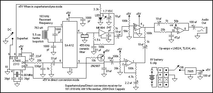
This is a description of an experimental AM receiver for VLF. It is crystal controlled to receive 181.818 kHz (more or less) and operates as either a single conversion superhetrodyne or a direct conversion receiver. The bandwidths are expected to...
Amatorki projekt
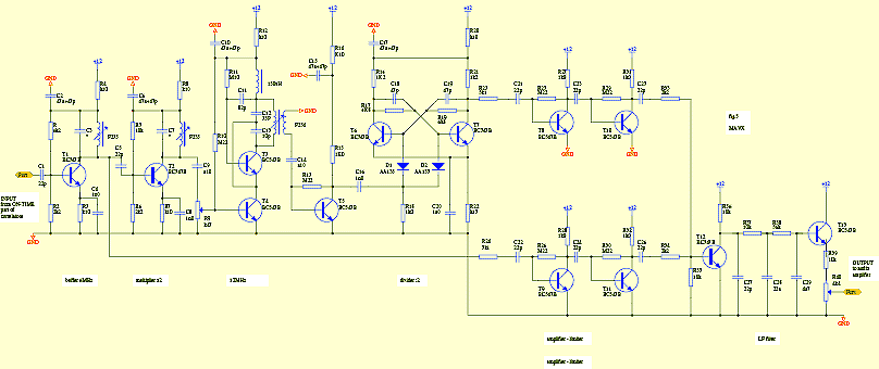
The circuit is designed to add two identical branches to the existing despreading spectrum. The only difference between the branches is the phase of the PN sequences fed into each branch, specifically at the input of a double-balanced mixer. The...
Carrier-current-am-receiver
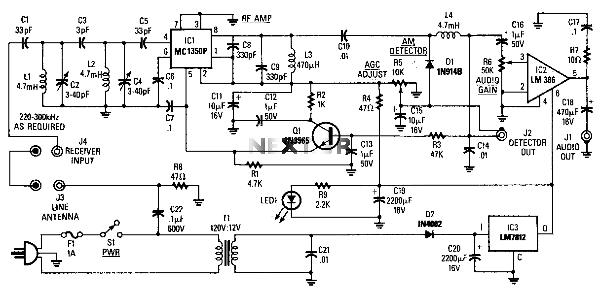
The AM Tuned Radio Frequency (TRF) receiver has a sensitivity of approximately 1 mV at the input for an audio output of 1/2 W. Capacitor C22 couples audio signals from the power line to the PC board and must be...
Rf power meter
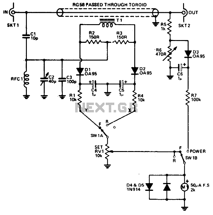
The reflectometer (SWR power meter) operates across three decades, ranging from 100 kHz to 100 MHz. It can be designed to handle RF power levels as low as 500 mW and up to 500 watts.
The reflectometer, also known as a...
Radio Frequency Circuits
This page is provided to the domain owner free by Sedo's Domain Parking. Disclaimer: The domain owner and Sedo maintain no relationship with third-party advertisers. References to any specific service or trademark are not controlled by Sedo or the domain...
RF Based Wireless Remote Control Switch
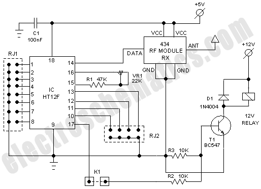
It is often necessary to control electrical appliances remotely, even when there is no direct line of sight between the transmitter and receiver.
In modern electronic applications, remote control systems are increasingly utilized for various purposes, including home automation, industrial control,...

Rf-Type Battery Charger Circuit
This type of charger transfers RF energy from an inductor (L2) to an external pickup coil. The pickup coil is connected to a rectifier and a battery that requires charging. This design is advantageous as it eliminates the need for...
GBPPR 1 GHz RF Spectrum Analyzer
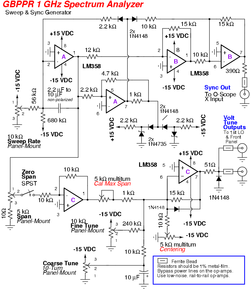
An RF spectrum analyzer is an essential tool for experimenters. The spectrum analyzer project described here is an enhancement of the "Spectrum Analyzer for the Radio Amateur" (Part 2) project by Wes Hayward (W7ZOI) and Terry White (K7TAU), which appeared...