


SpecAl <77> SpecAn
#spectrum analyser
#RF
#MC3356
#radio communication
#frequency analysis
#signal processing
#electronics design
#ham radio
#circuit adaptation
Description: A spectrum analyzer was built based on a design by Roger Blackwell, G4PMK, from the Radio Communication Handbook. The original design required adaptation due to the unavailability of the Motorola MC 3356 integrated circuit. The resulting analyzer is a dual conversion superheterodyne that accepts input signals ranging from DC to 50 MHz. These signals are first up-converted to a first intermediate frequency (IF) of 170 MHz, where they undergo amplification and filtering before being down-converted to a second IF of 10.7 MHz. The first IF was selected to match a helical filter on hand, although other frequencies could be utilized. The crystal filter defines the resolution bandwidth, while the helical filter, with a bandwidth of 2 MHz, is used to eliminate spurious responses. Without this filter, spurious signals appear at specific frequencies due to VCO harmonics. The design process was experimental, allowing for adjustments in gain and ensuring that each module was tested independently. Two versions of the second IF were constructed to evaluate different crystal filters. The voltage-controlled oscillator (VCO) is a varicap-controlled FET LC oscillator with an emitter-follower buffer, while amplification is achieved using cascaded MSA-0404 MMICs. A recommendation is made to use a commercial VCO for improved performance. The second local oscillator employed a 5th overtone Butler circuit with a custom 159.3 MHz crystal. Ground plane construction was used for all RF circuitry, with SMA connectors and mini coaxial cables for signal routing. The boards were drilled manually, and component sourcing is discussed, noting that the NE604 has been discontinued but can be replaced with the SA614AN. The sweep generator circuit features a 555 timer for controlling the sweep rate and generating a ramp signal, with various variable resistors for adjusting the sweep width and center frequency.
The spectrum analyzer operates as a dual conversion superheterodyne system, designed to analyze frequency components of signals within the range of DC to 50 MHz. The first stage involves up-converting these signals to an intermediate frequency of 170 MHz. This process utilizes a mixer, typically an NE602, which facilitates frequency translation while maintaining signal integrity. The amplified output is then filtered through a helical filter, which is critical in minimizing unwanted spurious signals that could interfere with the analysis.
The choice of a 170 MHz first IF was strategic, allowing the use of a specific helical filter while ensuring that the overall design remains flexible for future modifications. The second IF of 10.7 MHz allows for further signal processing and is a common choice in many RF applications due to its compatibility with standard filtering techniques.
The VCO design employs a varicap-controlled FET LC oscillator, providing a stable frequency output essential for accurate spectrum analysis. The cascaded MSA-0404 MMIC amplifiers are chosen for their high gain and low noise characteristics, which are crucial for maintaining the integrity of the signal throughout the processing stages. The recommendation to utilize a commercial VCO, such as the Mini-Circuits POS-300, is based on its compact design and superior performance metrics, which can simplify the implementation and enhance reliability.
The construction of the circuit emphasizes the importance of proper grounding and shielding to minimize noise interference. Ground plane techniques are employed to ensure that RF circuitry remains stable and performs efficiently. The use of SMA connectors and mini coaxial cables for inter-module connections further enhances signal quality by reducing loss and potential reflections.
The sweep generator circuit, driven by a 555 timer, is responsible for controlling the frequency sweep of the analyzer. This circuit generates a ramp signal that is applied to the VCO, allowing for systematic scanning across the desired frequency range. Variable resistors are utilized for fine-tuning the sweep parameters, providing flexibility in operation.
In conclusion, the described spectrum analyzer represents a well-thought-out design that balances performance and practicality. With considerations for component selection, construction techniques, and circuit design, it serves as a valuable tool for RF analysis and experimentation. Future iterations could benefit from the integration of advanced components and additional features to further enhance functionality.I decided to try my hand at building a spectrum analyser after seeing the design by Roger Blackwell, G4PMK, in the Radio Communication Handbook5. I had to adapt the design because I couldn`t get the Motorola MC 3356 IC he used. This is an account of what I came up with, how it performed and how it could be improved. Figure 1 is a block diagram of the analyser. It`s a dual conversion superhet. Input signals in the range DC to 50 MHz are up converted to a first IF of 170 MHz where they are amplified and filtered before being down converted to a second IF of 10. 7 MHz. The first IF was chosen to suit a helical filter I had in stock. There`s no reason why another frequency (e. g. 145 MHz) couldn`t be used instead. The crystal filter determines the resolution bandwidth. The helical filter has a bandwidth of 2MHz and serves only to remove spurious responses. Without it there are spurs at 26. 45, 31. 8, 38. 833, 45. 967 and 63. 6 MHz where VCO harmonics fall exactly 10. 7 MHz above or below harmonics of the second local oscillator. The 31. 8 MHz response is generated via an amazing intermediate frequency of 4 * (170 + 31. 8) = 10. 7 + 5 * 159. 3 = 807. 2 MHz showing what the NE602 mixer is capable of. Why so many The design was experimental. I didn`t know how much gain would be needed to raise the VCO output to the required level until I`d built and tested it; and I didn`t want to put too much on one board in case something went wrong!
Each module was tested separately. I built two versions of the second IF to try different crystal filters. The VCO is a varicap-controlled FET LC oscillator with an emitter-follower buffer. The amplifier is a pair of cascaded MSA-0404 MMICs. I`m not going to describe these two modules in greater detail because I recommend using a commercial VCO such as the Mini-Circuits POS-300 instead. This can be mounted adjacent to the first mixer. Its compactness, frequency span and linearity are unbeatable. I won`t describe the second local oscillator either except to say it was a 5th overtone butler circuit using a made to order 159.
3 MHz crystal. Next time, I`ll use the NE602 internal oscillator, which, according to a Philips application note3, is reliable up to the 7th overtone. It isn`t the best mixer at 170 MHz, it`s noisy and the input match is tricky from 50 ohms, but it`s simple.
You could even use a LC oscillator. Ground plane construction was used for all RF circuitry. The front-end was built on double-sided copper clad board. Single sided board was used for the other RF modules. SMA connectors and mini coax were used to route signals between the boards. Drilling templates were marked out on 0. 1" graph paper. These could be done on a computer but one-offs are quicker by hand. I just pushed the legs of the helical filter through the paper. The boards were drilled with a craft drill. Copper was cleared around the holes using a Vero tool. Heat breaks were scored with a scalpel to make soldering to the top easier. Regarding sourcing of components, the DIP16 packaged NE604 has been discontinued; but the pin-compatible SA614AN is a superior alternative. I find Barend Hendriksen1 in Holland a very useful source for specialist RF components. I recommend Sycom2 in the UK. SMA bits can often be picked up cheaply at rallies. The sweep generator schematic is shown in figure 2. 555 timer U1 controls the sweep rate. VR1 sets the speed. Integrator U2 generates the ramp. VR2 sets the sweep width. VR3 and VR4 set the display centre frequency. A 10-turn pot could be used instead, but large frequency changes are faster with separate coarse and fine controls.
The sweep output on U4 pin 6 is directly connected to the VCO control input. The oscilloscope is triggered using the flyback pulses on U1 pin 3. Spectrum analyser circuits usually show the `scope`s X input driven by a ramp but my `scope doesn`t have an X input! Smoothing on U5 pin 3 is essential for a sh
The spectrum analyzer operates as a dual conversion superheterodyne system, designed to analyze frequency components of signals within the range of DC to 50 MHz. The first stage involves up-converting these signals to an intermediate frequency of 170 MHz. This process utilizes a mixer, typically an NE602, which facilitates frequency translation while maintaining signal integrity. The amplified output is then filtered through a helical filter, which is critical in minimizing unwanted spurious signals that could interfere with the analysis.
The choice of a 170 MHz first IF was strategic, allowing the use of a specific helical filter while ensuring that the overall design remains flexible for future modifications. The second IF of 10.7 MHz allows for further signal processing and is a common choice in many RF applications due to its compatibility with standard filtering techniques.
The VCO design employs a varicap-controlled FET LC oscillator, providing a stable frequency output essential for accurate spectrum analysis. The cascaded MSA-0404 MMIC amplifiers are chosen for their high gain and low noise characteristics, which are crucial for maintaining the integrity of the signal throughout the processing stages. The recommendation to utilize a commercial VCO, such as the Mini-Circuits POS-300, is based on its compact design and superior performance metrics, which can simplify the implementation and enhance reliability.
The construction of the circuit emphasizes the importance of proper grounding and shielding to minimize noise interference. Ground plane techniques are employed to ensure that RF circuitry remains stable and performs efficiently. The use of SMA connectors and mini coaxial cables for inter-module connections further enhances signal quality by reducing loss and potential reflections.
The sweep generator circuit, driven by a 555 timer, is responsible for controlling the frequency sweep of the analyzer. This circuit generates a ramp signal that is applied to the VCO, allowing for systematic scanning across the desired frequency range. Variable resistors are utilized for fine-tuning the sweep parameters, providing flexibility in operation.
In conclusion, the described spectrum analyzer represents a well-thought-out design that balances performance and practicality. With considerations for component selection, construction techniques, and circuit design, it serves as a valuable tool for RF analysis and experimentation. Future iterations could benefit from the integration of advanced components and additional features to further enhance functionality.I decided to try my hand at building a spectrum analyser after seeing the design by Roger Blackwell, G4PMK, in the Radio Communication Handbook5. I had to adapt the design because I couldn`t get the Motorola MC 3356 IC he used. This is an account of what I came up with, how it performed and how it could be improved. Figure 1 is a block diagram of the analyser. It`s a dual conversion superhet. Input signals in the range DC to 50 MHz are up converted to a first IF of 170 MHz where they are amplified and filtered before being down converted to a second IF of 10. 7 MHz. The first IF was chosen to suit a helical filter I had in stock. There`s no reason why another frequency (e. g. 145 MHz) couldn`t be used instead. The crystal filter determines the resolution bandwidth. The helical filter has a bandwidth of 2MHz and serves only to remove spurious responses. Without it there are spurs at 26. 45, 31. 8, 38. 833, 45. 967 and 63. 6 MHz where VCO harmonics fall exactly 10. 7 MHz above or below harmonics of the second local oscillator. The 31. 8 MHz response is generated via an amazing intermediate frequency of 4 * (170 + 31. 8) = 10. 7 + 5 * 159. 3 = 807. 2 MHz showing what the NE602 mixer is capable of. Why so many The design was experimental. I didn`t know how much gain would be needed to raise the VCO output to the required level until I`d built and tested it; and I didn`t want to put too much on one board in case something went wrong!
Each module was tested separately. I built two versions of the second IF to try different crystal filters. The VCO is a varicap-controlled FET LC oscillator with an emitter-follower buffer. The amplifier is a pair of cascaded MSA-0404 MMICs. I`m not going to describe these two modules in greater detail because I recommend using a commercial VCO such as the Mini-Circuits POS-300 instead. This can be mounted adjacent to the first mixer. Its compactness, frequency span and linearity are unbeatable. I won`t describe the second local oscillator either except to say it was a 5th overtone butler circuit using a made to order 159.
3 MHz crystal. Next time, I`ll use the NE602 internal oscillator, which, according to a Philips application note3, is reliable up to the 7th overtone. It isn`t the best mixer at 170 MHz, it`s noisy and the input match is tricky from 50 ohms, but it`s simple.
You could even use a LC oscillator. Ground plane construction was used for all RF circuitry. The front-end was built on double-sided copper clad board. Single sided board was used for the other RF modules. SMA connectors and mini coax were used to route signals between the boards. Drilling templates were marked out on 0. 1" graph paper. These could be done on a computer but one-offs are quicker by hand. I just pushed the legs of the helical filter through the paper. The boards were drilled with a craft drill. Copper was cleared around the holes using a Vero tool. Heat breaks were scored with a scalpel to make soldering to the top easier. Regarding sourcing of components, the DIP16 packaged NE604 has been discontinued; but the pin-compatible SA614AN is a superior alternative. I find Barend Hendriksen1 in Holland a very useful source for specialist RF components. I recommend Sycom2 in the UK. SMA bits can often be picked up cheaply at rallies. The sweep generator schematic is shown in figure 2. 555 timer U1 controls the sweep rate. VR1 sets the speed. Integrator U2 generates the ramp. VR2 sets the sweep width. VR3 and VR4 set the display centre frequency. A 10-turn pot could be used instead, but large frequency changes are faster with separate coarse and fine controls.
The sweep output on U4 pin 6 is directly connected to the VCO control input. The oscilloscope is triggered using the flyback pulses on U1 pin 3. Spectrum analyser circuits usually show the `scope`s X input driven by a ramp but my `scope doesn`t have an X input! Smoothing on U5 pin 3 is essential for a sh
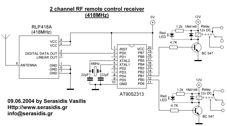
2 channel RF remote control
The basic small-range remote controls are Infrared and RF (Radio Frequency). One of the weaknesses of Infrared is that the signal cannot pass through walls. Therefore, to control a garage door, an RF remote control is necessary. The circuit (transmitter...
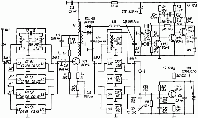
HAM RADIO SW RECEIVER
A simple radio receiver circuit is illustrated. This receiver is designed to capture signals from amateur radio stations operating in the shortwave (SW) bands of 10, 15, 20, 40, and 80 meters. The direct-conversion receiver comprises a set of input...
RF Circuitry Links
The 7th overtone of 18 MHz (17m) is 144 MHz (2m) directly within the CW region. Icarus is a high-altitude balloon (HAB) project funded by advertising revenue, which has successfully launched numerous balloons that captured impressive photographs. Robert Harrison is...
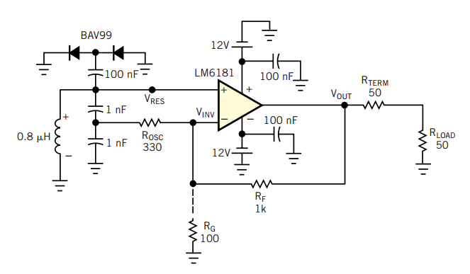
RF oscillator uses current-feedback op amp
A current-feedback amplifier is a well-known component with many uses. Its basic block diagram shows that its input stage is a voltage follower in practice, a symmetrical emitter follower. The configuration samples the output current, converts it to voltage across...
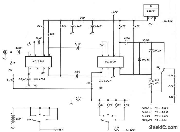
SENSITIVE RF VOLTMETER
This schematic illustrates a peak-reading diode voltmeter that is powered by two amplification stages. A 100 µF capacitor is utilized to create a substantial time constant, which ensures effective damping of the meter. The restricted differential output voltage, combined with...
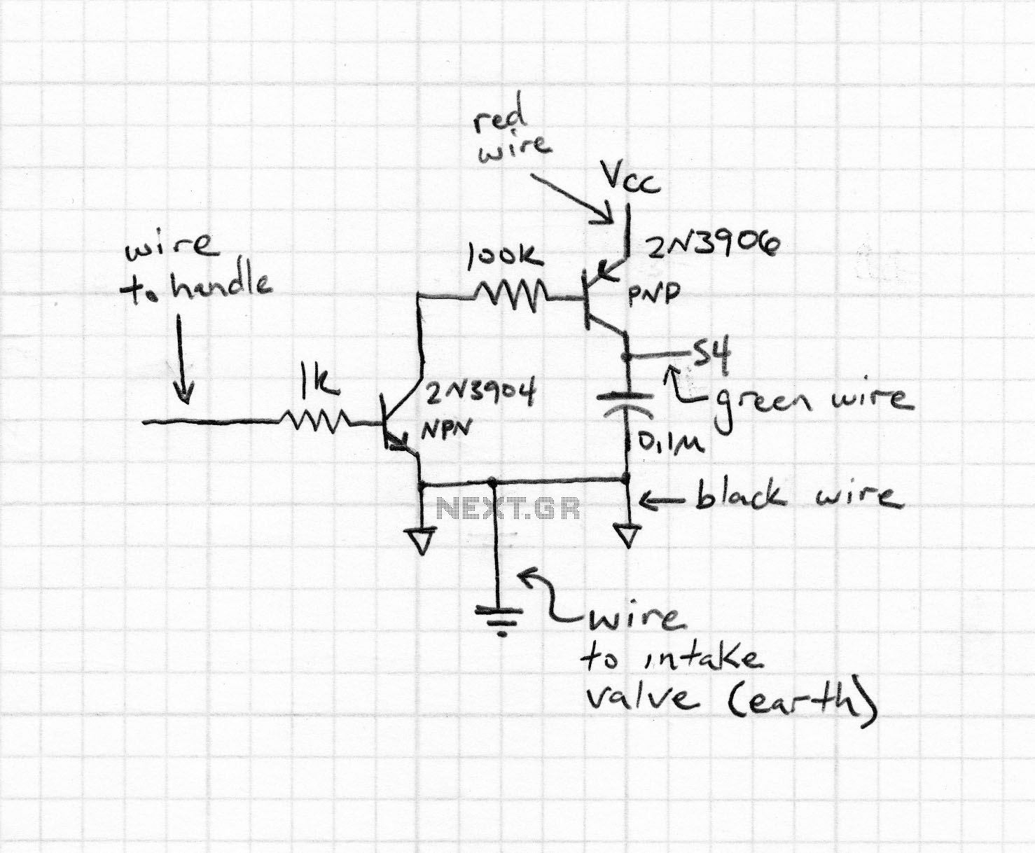
RF field strength meter
A simple Field Strength Meter consists of a small antenna, a detector diode, a resistor, a capacitor, and a micro ammeter. This circuit is sensitive enough to detect HF fields when positioned close to the transmitting antenna. The circuit functioned...
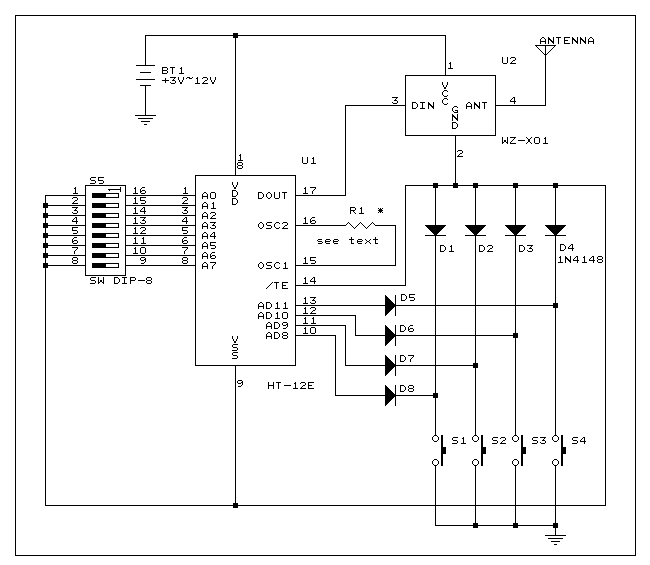
Four channel RF remote control
This is a simple RF transmitter circuit utilizing the Holtek HT-12E encoder chip and an AM 418MHz transmitter module (WZ-X01). The use of hybrid RF transmit/receive modules simplifies the construction of the RF remote control. The transmitter can operate with...
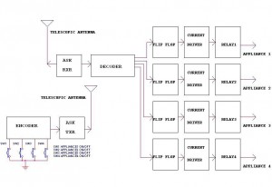
Remote ControlCircuit Through RF Without Microcontroller
This circuit illustrates a remote control circuit diagram using RF technology without the use of a microcontroller. Features include a simple remote control circuit that operates via radio frequency.
The remote control circuit operates by transmitting signals through radio waves, enabling...
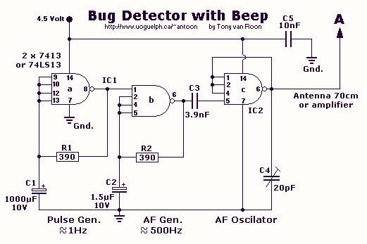
RF Bug detector
This circuit is not open for discussion. Although working perfectly, it was experimental. I will answer no emails in regards to this circuit. If you are looking for a more serious and reliable bug detector, go to the Countersurveillance Monitor...