


Stereo FM Transmitter with BA1404
#FM transmitter
#stereo modulator
#BA1404
#RF amplifier
#pre-emphasis network
#oscillator frequency
#channel separation
#38kHz crystal
#composite stereo signal
#ROHM Semiconductors
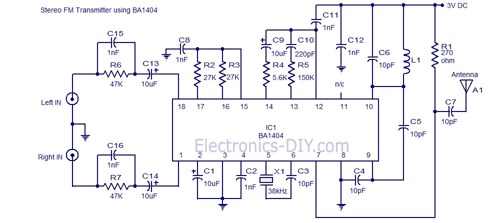
Description: A high-quality stereo FM transmitter circuit is presented. This circuit utilizes the BA1404 integrated circuit from ROHM Semiconductors. The BA1404 is a monolithic FM stereo modulator that includes a built-in stereo modulator, FM modulator, and RF amplifier. The FM modulator operates within a frequency range of 76 to 108 MHz, and the power supply for the circuit can vary from 1.25 to 3 volts. In this circuit, components R7, C16, C14, and R6, C15, C13 form the pre-emphasis network for the right and left audio channels, respectively. This configuration is designed to match the frequency response of the FM transmitter with that of the FM receiver. Inductor L1 and capacitor C5 are employed to set the oscillator frequency. The network comprising C9, C10, R4, and R5 enhances channel separation. A 38 kHz crystal (X1) is connected between pins 5 and 6 of the IC, facilitating the creation of a composite stereo signal through the stereo modulator circuit, which operates using the quartz-controlled frequency.
The high-quality stereo FM transmitter circuit based on the BA1404 IC is designed to provide efficient transmission of audio signals with minimal distortion and optimal stereo separation. The BA1404 integrates multiple functionalities, which simplifies the overall design while ensuring robust performance. The operating frequency range of 76 to 108 MHz is suitable for standard FM broadcasting, making this circuit applicable for various audio transmission projects.
The pre-emphasis network, composed of resistors (R6, R7) and capacitors (C13, C14, C15, C16), is crucial for enhancing the signal-to-noise ratio during transmission. By boosting higher frequencies, this network compensates for the inherent limitations of FM receivers, which typically exhibit reduced sensitivity to high-frequency audio components. This careful tuning ensures that the transmitted audio maintains clarity and fidelity when received.
The oscillator circuit, formed by inductor L1 and capacitor C5, determines the carrier frequency of the FM signal. The precise selection of these components is essential, as it directly influences the stability and quality of the transmitted signal. The inclusion of the 38 kHz crystal (X1) provides a stable reference frequency, which is fundamental for generating a consistent composite stereo signal. This reference frequency is pivotal for ensuring that the stereo modulator operates effectively, allowing for accurate transmission of stereo audio signals.
The additional network comprising capacitors (C9, C10) and resistors (R4, R5) plays a significant role in improving channel separation, which is vital for maintaining the integrity of the left and right audio channels. This enhancement minimizes crosstalk between channels, ensuring that the listener experiences a clear and distinct stereo soundstage.
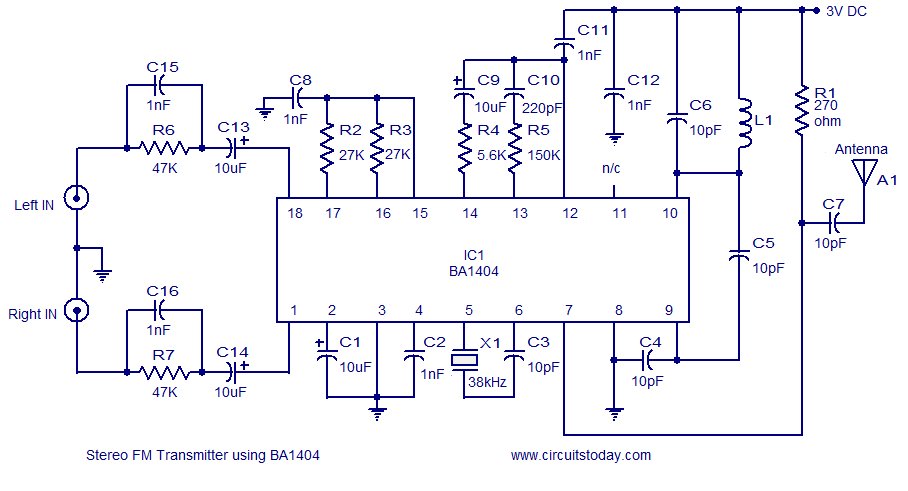
Overall, this stereo FM transmitter circuit exemplifies a well-engineered solution for audio transmission, combining advanced modulation techniques with careful component selection to achieve high-quality performance in FM broadcasting applications.A high quality stereo FM transmitter circuit is shown here. The circuit is based on the IC BA1404 from ROHM Semiconductors. BA1404 is a monolithic FM stereo modulator that has built in stereo modulator, FM modulator and RF amplifier. The FM modulator can be operated from 76 to 108MHz and power supply for the circuit can be anything between 1.25 to 3 volts.
In the circuit R7, C16, C14 and R6, C15, C13 forms the pre-emphasis network for the right and left channels respectively. This is done for matching the frequency response of the FM transmitter with the FM receiver. Inductor L1 and capacitor C5 is used to set the oscillator frequency. Network C9,C10, R4,R5 improves the channel separation. 38kHz crystal X1 is connected between pins 5 and 6 of the IC. Composite stereo signal is created by the stereo modulator circuit using the 38kHz quartz controlled frequency
The high-quality stereo FM transmitter circuit based on the BA1404 IC is designed to provide efficient transmission of audio signals with minimal distortion and optimal stereo separation. The BA1404 integrates multiple functionalities, which simplifies the overall design while ensuring robust performance. The operating frequency range of 76 to 108 MHz is suitable for standard FM broadcasting, making this circuit applicable for various audio transmission projects.
The pre-emphasis network, composed of resistors (R6, R7) and capacitors (C13, C14, C15, C16), is crucial for enhancing the signal-to-noise ratio during transmission. By boosting higher frequencies, this network compensates for the inherent limitations of FM receivers, which typically exhibit reduced sensitivity to high-frequency audio components. This careful tuning ensures that the transmitted audio maintains clarity and fidelity when received.
The oscillator circuit, formed by inductor L1 and capacitor C5, determines the carrier frequency of the FM signal. The precise selection of these components is essential, as it directly influences the stability and quality of the transmitted signal. The inclusion of the 38 kHz crystal (X1) provides a stable reference frequency, which is fundamental for generating a consistent composite stereo signal. This reference frequency is pivotal for ensuring that the stereo modulator operates effectively, allowing for accurate transmission of stereo audio signals.
The additional network comprising capacitors (C9, C10) and resistors (R4, R5) plays a significant role in improving channel separation, which is vital for maintaining the integrity of the left and right audio channels. This enhancement minimizes crosstalk between channels, ensuring that the listener experiences a clear and distinct stereo soundstage.
Overall, this stereo FM transmitter circuit exemplifies a well-engineered solution for audio transmission, combining advanced modulation techniques with careful component selection to achieve high-quality performance in FM broadcasting applications.A high quality stereo FM transmitter circuit is shown here. The circuit is based on the IC BA1404 from ROHM Semiconductors. BA1404 is a monolithic FM stereo modulator that has built in stereo modulator, FM modulator and RF amplifier. The FM modulator can be operated from 76 to 108MHz and power supply for the circuit can be anything between 1.25 to 3 volts.
In the circuit R7, C16, C14 and R6, C15, C13 forms the pre-emphasis network for the right and left channels respectively. This is done for matching the frequency response of the FM transmitter with the FM receiver. Inductor L1 and capacitor C5 is used to set the oscillator frequency. Network C9,C10, R4,R5 improves the channel separation. 38kHz crystal X1 is connected between pins 5 and 6 of the IC. Composite stereo signal is created by the stereo modulator circuit using the 38kHz quartz controlled frequency

FM Bug Transmitter Mint Box Circuit
This circuit represents an FM transmitter, also referred to as an FM Bug, which consists of 18 essential components for optimal functionality. The circuit begins with an electret microphone on the far left side, and the signal flows electrically to...
High quality Stereo FM transmitter using BA1404
A simple and high-quality FM transmitter circuit designed based on the BA1404 IC. This FM transmitter circuit can be operated from a 3 V battery.
The FM transmitter circuit utilizing the BA1404 integrated circuit (IC) is engineered for simplicity and efficiency,...

Low Cost 1000 Watt 300 Volt Rf Power Amplifier For 27.12mhz
The LinkSwitch-TN supply LNK306PN provides a constant current output of up to 9 W at a maximum output voltage of 70 VDC, making it suitable for driving LEDs. A passive valley-fill power factor correction (PFC) circuit ensures the supply achieves...
1.5v wireless fm transmitter circuit
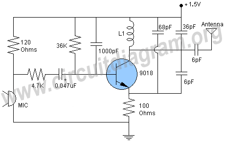
A simple whole house FM transmitter circuit diagram and description. Operating power is a 1.5V battery of any type. This circuit is able to transmit at a distance of 30 meters.
The whole house FM transmitter circuit operates on a low...

1.3W RF Amplifier
This diagram represents a schematic of an RF amplifier circuit. The circuit is designed to amplify an RF signal from approximately 100 mW input power to 1.3 W output power. It utilizes a general NPN RF transistor, specifically the 2SC1970....

3v fm transmitter for short distance
The core component of the circuit is a Colpitts type oscillator. The capacitors C3, C4, C5, C6, diodes CD1-CD2, and inductor L1 determine the oscillation frequency. The active components in the oscillator include the BF982 and a dual-gate MOSFET. When...

Single Chip FM Transmitter Circuit
A simple FM transmitter connects a home entertainment system to a portable radio that can be moved around the house and into the backyard. For instance, music can be played from a CD player in the living room and listened...
Wideband RF Amplifier
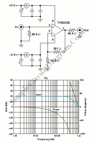
This circuit consists of wideband RF amplifiers that utilize current-feedback components such as the THS3202. The THS3202 was selected for its fast slew rate and wide bandwidth. The amplifier voltage gain of this circuit is 20, while the stage voltage...
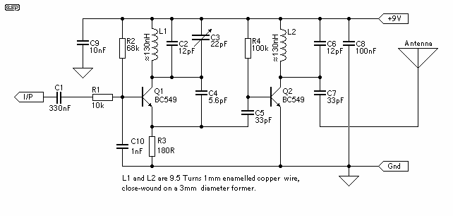
Low Power FM Transmitter
The circuit of the transmitter is shown in Figure 1, and as you can see it is quite simple. The first stage is the oscillator, and is tuned with the variable capacitor. Select an unused frequency, and carefully adjust C3...