


The FSK modulation circuit composed of 74LS74
#FSK modulation
#74LS74
#tune circuit
#frequency band
#high-frequency
#digital logic
#communication
#signal processing
#modulation
#filter
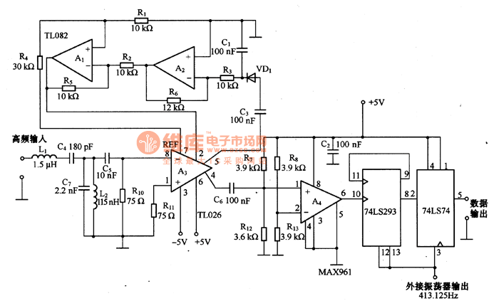
Description: This is an FSK modulation circuit composed of the 74LS74. The FSK modulation circuit does not include a phase-locked loop (PLL) or a high-Q bandpass filter, eliminating the need for tuning adjustments in the high-frequency modulation circuit. The two tuning circuits, consisting of L1, L2, C4, and C7, function as an input filter, allowing only the frequency band with a central frequency of 10 MHz to pass through. The high-frequency difference amplifier A3 amplifies the 10 MHz signal. The automatic gain control (AGC) circuit is composed of A1 and A2. The high-frequency signal, amplified by A3, can be converted into a digital signal by comparator A4.
The FSK modulation circuit utilizing the 74LS74 flip-flop is designed for efficient frequency shift keying applications. The absence of a phase-locked loop (PLL) simplifies the design, making it more robust against variations in frequency due to environmental factors. The high-Q bandpass filter is also omitted, which further streamlines the circuit and reduces complexity.
The input filter, formed by the inductors L1 and L2 and capacitors C4 and C7, is critical in ensuring that only the desired frequency of 10 MHz is processed. This filter is designed to reject unwanted frequencies, thus enhancing the performance of the modulation circuit by minimizing noise and interference.
Amplifier A3 serves as a high-frequency difference amplifier, effectively increasing the amplitude of the 10 MHz signal, which is essential for subsequent processing stages. The gain provided by A3 is crucial for maintaining signal integrity and ensuring that the signal is strong enough for digital conversion.
The automatic gain control (AGC) circuit, comprising amplifiers A1 and A2, plays a vital role in maintaining consistent output levels despite variations in input signal strength. This feature is particularly important in communication systems where signal levels can fluctuate due to various factors, including distance and environmental conditions.
Finally, comparator A4 is employed to convert the amplified analog signal into a digital format. This conversion is essential for digital processing and ensures that the FSK modulation can be effectively utilized in digital communication systems. The overall design of the circuit emphasizes efficiency and reliability, making it suitable for a range of applications in modern electronics.This is the FSK modulation circuit composed of 74LS74. The FSK modulation circuit has neither PLL nor bandpass filter with high Q value, so there is no need of any tune adjustment in the high-frequency modulation circuit. The 2 tune circuits composed of L1, L2, C4 and C7 is working as the input filter, which only allows the frequency band with cen
tral frequency of 10MHZ to pass, and the high frequency difference amplifier A3 can amplify the 10MHZ signal. The auto gain control (AGC) circuit is composed of A1 and A2. The HF signal, which is magnified by A3, can be switched into digital signal by comparator A4.
The FSK modulation circuit utilizing the 74LS74 flip-flop is designed for efficient frequency shift keying applications. The absence of a phase-locked loop (PLL) simplifies the design, making it more robust against variations in frequency due to environmental factors. The high-Q bandpass filter is also omitted, which further streamlines the circuit and reduces complexity.
The input filter, formed by the inductors L1 and L2 and capacitors C4 and C7, is critical in ensuring that only the desired frequency of 10 MHz is processed. This filter is designed to reject unwanted frequencies, thus enhancing the performance of the modulation circuit by minimizing noise and interference.
Amplifier A3 serves as a high-frequency difference amplifier, effectively increasing the amplitude of the 10 MHz signal, which is essential for subsequent processing stages. The gain provided by A3 is crucial for maintaining signal integrity and ensuring that the signal is strong enough for digital conversion.
The automatic gain control (AGC) circuit, comprising amplifiers A1 and A2, plays a vital role in maintaining consistent output levels despite variations in input signal strength. This feature is particularly important in communication systems where signal levels can fluctuate due to various factors, including distance and environmental conditions.
Finally, comparator A4 is employed to convert the amplified analog signal into a digital format. This conversion is essential for digital processing and ensures that the FSK modulation can be effectively utilized in digital communication systems. The overall design of the circuit emphasizes efficiency and reliability, making it suitable for a range of applications in modern electronics.This is the FSK modulation circuit composed of 74LS74. The FSK modulation circuit has neither PLL nor bandpass filter with high Q value, so there is no need of any tune adjustment in the high-frequency modulation circuit. The 2 tune circuits composed of L1, L2, C4 and C7 is working as the input filter, which only allows the frequency band with cen
tral frequency of 10MHZ to pass, and the high frequency difference amplifier A3 can amplify the 10MHZ signal. The auto gain control (AGC) circuit is composed of A1 and A2. The HF signal, which is magnified by A3, can be switched into digital signal by comparator A4.
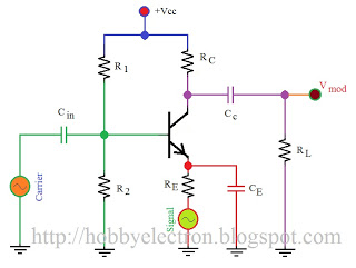
modulation is process of changing
Modulation is the process of altering certain characteristics (such as amplitude, frequency, or phase) of a carrier wave in accordance with the intensity of the signal. The provided figure illustrates the electronic circuit of a simple amplitude modulation (AM) modulator....
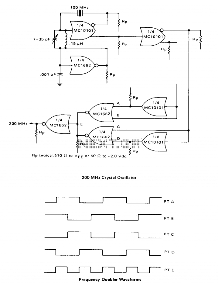
High-frequency crystal oscillator
A high-speed oscillator can be created by integrating an MECL 10 crystal oscillator with an MECL III frequency doubler. One section of the MC10101 is configured as a 100 MHz crystal oscillator, with the crystal placed in series within the...
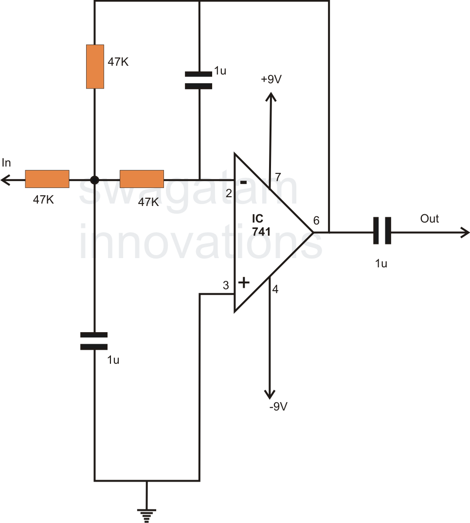
how to make simple active low pass
In electronics, filter circuits are primarily used to restrict the passage of certain frequency ranges while allowing other frequency bands to proceed to subsequent stages of the circuit. A high-pass filter circuit permits only frequencies that exceed a specified range,...
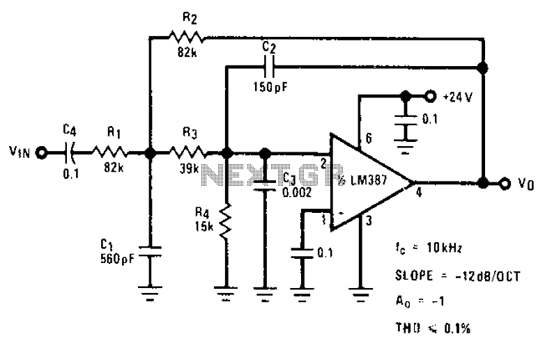
Stylus sand acoustic filter circuit diagrams
The circuit provides a passband gain of 1 with a corner frequency of 10 kHz, designed to eliminate high-frequency noise such as hiss, ticking, and popping sounds.
This circuit operates as a low-pass filter, effectively attenuating frequencies above the specified corner...
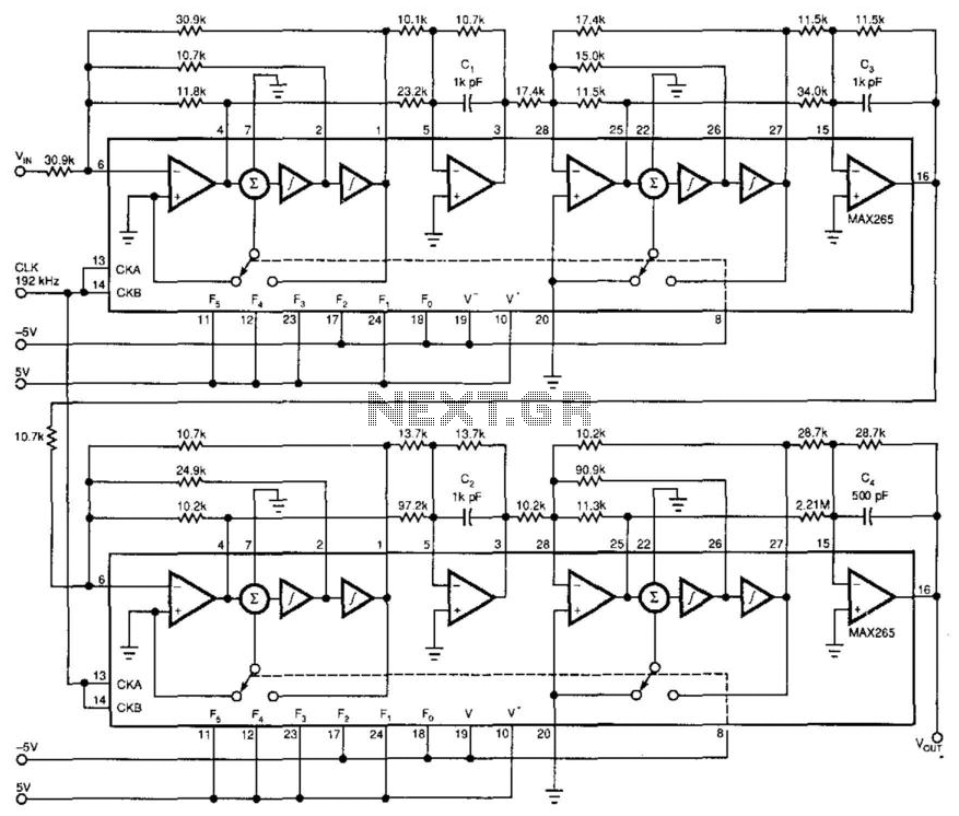
Antialiasing And Sync-Compensation Filter
Two dual-biquad filter chips and some external components form a multipurpose filter to reconstruct D/A converter signals. Connected to a converter's output, the filter provides antialiasing, reduces the D/A converter's quantization noise, and compensates for the "sync" function (attenuation). The...
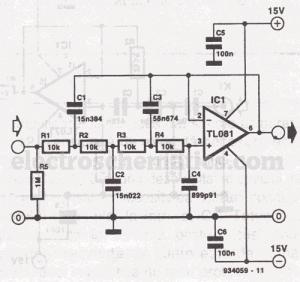
4 order filter with a single IC project PCB
High-order circuit filters are typically designed using two or more cascaded sections. This fourth-order filter requires only one operational amplifier (OA) integrated circuit (IC), which helps achieve lower distortion and reduced intermodulation. The resistor values represent the load on the...

Digital Electronics Education
The goal of Advanced Digital Electronics courses is to connect basic logic gates (combinational circuits) with technical subjects related to binary counter topologies (both Asynchronous and Synchronous), shift registers, memory, and Digital Signal Processors (DSP), which are categorized as sequential...
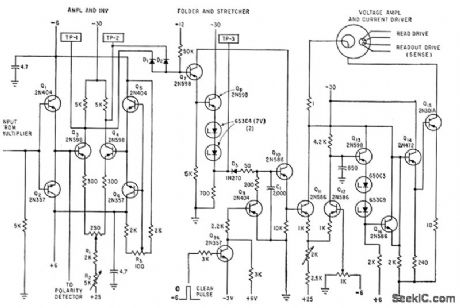
ROTARY SWITCH DEBOUNCE
A three-stage active Butterworth bandpass input filter is utilized in a radioteletype demodulator to differentiate RTTY tones from one another and from noise. The filter is centered at 2200 Hz and has a bandwidth of approximately 260 Hz, allowing for...

nescaf
The NEScaf filter is designed to offer greater flexibility than previous filters for QRP (low-power) radio rigs. It features two panel-mounted controls: a single center-detent potentiometer that adjusts the center frequency of the filter's bandpass (settable between approximately 415 Hz...