


Triple/Dual/Single Mode CDMA LNA/Mixers Receiver System Requirements
#CDMA
#LNA
#mixer
#receiver
#RF
#low noise amplifier
#down converter
#wireless communication
#telecommunication
#system specification
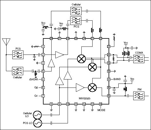
Description: This technical note focuses on determining the system specifications of a CDMA receiver to establish practical specifications for a low noise amplifier and down converter.
The design of a CDMA (Code Division Multiple Access) receiver necessitates a comprehensive understanding of its system specifications, which are critical for the effective performance of associated components, such as a low noise amplifier (LNA) and a down converter. The specifications must account for various factors, including the desired signal-to-noise ratio (SNR), frequency range, and the required linearity of the LNA.
To begin with, the frequency range of the CDMA signals must be identified. CDMA systems typically operate within specific frequency bands, which vary based on regulatory requirements and the intended application. The LNA must be designed to amplify signals within this range while minimizing noise. The noise figure (NF) of the LNA is a crucial parameter, as it directly impacts the overall SNR of the receiver. A low NF is essential for enhancing the sensitivity of the receiver, allowing it to detect weaker signals in the presence of noise.
In addition to the LNA, the down converter plays a pivotal role in the receiver architecture. Its primary function is to shift the frequency of the received signal to a lower intermediate frequency (IF) that is more manageable for further processing. The specifications for the down converter should include parameters such as conversion gain, image rejection, and linearity. The conversion gain must be sufficient to maintain the integrity of the signal while ensuring that the output does not exceed the input range of subsequent processing stages.
Furthermore, the design process involves simulations and calculations to validate the performance of both the LNA and the down converter under various operating conditions. This includes assessing the impact of temperature variations, supply voltage fluctuations, and potential interference from other signals. The end goal is to achieve a robust receiver design capable of reliable performance in real-world scenarios, ensuring that the CDMA receiver meets the necessary standards for communication quality and efficiency.This technical note is focused on how to determine the system specification of a CDMA receiver in order to establish a practical specification for a low noise amplifier and down converter..
The design of a CDMA (Code Division Multiple Access) receiver necessitates a comprehensive understanding of its system specifications, which are critical for the effective performance of associated components, such as a low noise amplifier (LNA) and a down converter. The specifications must account for various factors, including the desired signal-to-noise ratio (SNR), frequency range, and the required linearity of the LNA.
To begin with, the frequency range of the CDMA signals must be identified. CDMA systems typically operate within specific frequency bands, which vary based on regulatory requirements and the intended application. The LNA must be designed to amplify signals within this range while minimizing noise. The noise figure (NF) of the LNA is a crucial parameter, as it directly impacts the overall SNR of the receiver. A low NF is essential for enhancing the sensitivity of the receiver, allowing it to detect weaker signals in the presence of noise.
In addition to the LNA, the down converter plays a pivotal role in the receiver architecture. Its primary function is to shift the frequency of the received signal to a lower intermediate frequency (IF) that is more manageable for further processing. The specifications for the down converter should include parameters such as conversion gain, image rejection, and linearity. The conversion gain must be sufficient to maintain the integrity of the signal while ensuring that the output does not exceed the input range of subsequent processing stages.
Furthermore, the design process involves simulations and calculations to validate the performance of both the LNA and the down converter under various operating conditions. This includes assessing the impact of temperature variations, supply voltage fluctuations, and potential interference from other signals. The end goal is to achieve a robust receiver design capable of reliable performance in real-world scenarios, ensuring that the CDMA receiver meets the necessary standards for communication quality and efficiency.This technical note is focused on how to determine the system specification of a CDMA receiver in order to establish a practical specification for a low noise amplifier and down converter..

Transmitter RF Output LED Indicator
Transmitter RF Output LED Indicator Circuit Diagram. This RF output detector circuit, which includes a visual indicator, can be useful for an RF application.
The transmitter RF output LED indicator circuit is designed to provide a visual representation of the RF...
High Performance Regen Receiver
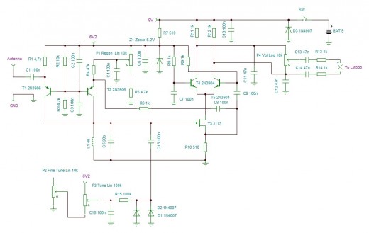
A new high-performance regenerative receiver is available as a kit. The inclusion of an innovative regenerative detector circuit enhances sensitivity and overall performance.
The regenerative receiver kit is designed to provide users with a high-quality radio frequency (RF) reception experience. The...
Simple Mixer with 4 Input
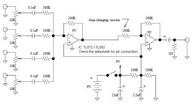
A basic mixer suitable for mixing microphones or effects outputs. The overall gain from input to output is unity if the potentiometer related to the input is fully turned up. This gain can be increased to ten (or any other...
RF oscillator uses current-feedback op amp
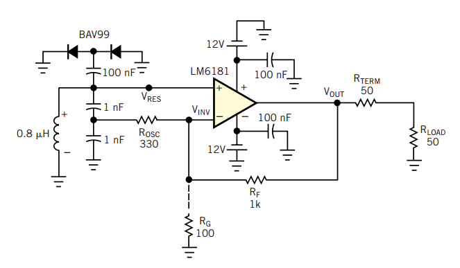
A current-feedback amplifier is a well-known component with many uses. Its basic block diagram shows that its input stage is a voltage follower in practice, a symmetrical emitter follower. The configuration samples the output current, converts it to voltage across...
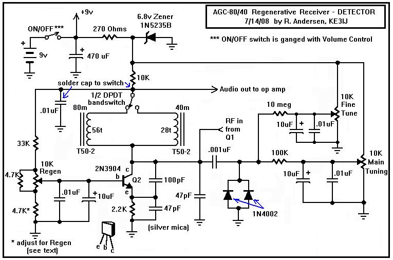
A Regenerative Receiver with AGC for 80 and 40 Meters
Here is a dual-band regenerative receiver that originated from encouraging communications with Jerry (K9UT) and another individual named Harvey, who constructed the original AGC-80 and its experimental successor, the AGC-80/30. Jerry has expressed his satisfaction with both receivers, noting their...
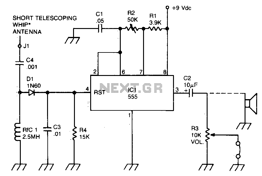
RF-powered sidetone oscillator
A sidetone oscillator is a specific type of audio astable multivibrator. Keying is achieved by turning the oscillator on and off through the application of a positive DC potential, which is generated from the RF signal to the reset terminal...
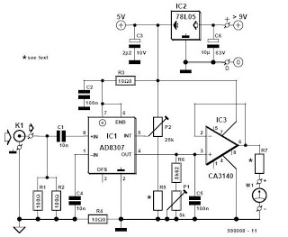
RF Decibel Meter
This is a zine dedicated to electronics circuit diagrams, DIY (do it yourself) electronics projects, electrical electronics data sheets, and microcontroller projects for hobbyists, students, consultants, and product designers.
The zine serves as a comprehensive resource for individuals interested in electronics,...
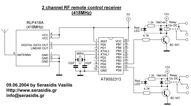
2 channel RF remote control
The basic small-range remote controls are Infrared and RF (Radio Frequency). One of the weaknesses of Infrared is that the signal cannot pass through walls. Therefore, to control a garage door, an RF remote control is necessary. The circuit (transmitter...

Compact DJ Station
The mixer is equipped with two stereo phono inputs and two stereo line-level inputs, along with a single stereo mixing channel. It includes a microphone input and a stereo main output with adjustable gain. The general circuit diagram displays all...