


tv transmitter circuit
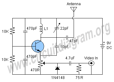
Description: Here is a simple schematic of a TV transmitter circuit, or video transmitter circuit, capable of broadcasting in the VHF range from 60 to 200 MHz. The input video source can be any CCD camera or VCR. The output power of this VHF transmitter circuit is 80 mW, and it employs a telescopic antenna. The circuit utilizes a single transistor, which can be a BC337, N2222, BC546, or BC108. For the inductor L1, six turns of #24 enameled wire should be wound on a 10 mm air former to achieve the desired frequency range of 60 to 80 MHz.
The described TV transmitter circuit operates within the VHF frequency range, making it suitable for short-range broadcasting applications. The primary components include a transistor, which serves as the active amplification element, and an inductor, which is crucial for tuning the circuit to the desired frequency. The choice of transistor—BC337, N2222, BC546, or BC108—provides flexibility in component selection based on availability and performance characteristics. Each of these transistors has suitable gain and frequency response for this application.
The inductor L1, wound with six turns of #24 enameled wire on a 10 mm air former, is essential for the oscillation and frequency stability of the transmitter. The number of turns and the diameter of the former directly influence the inductance value, which in turn affects the resonant frequency of the circuit. It is important to ensure that the inductor is properly constructed to minimize losses and maintain efficiency.
The output power of 80 mW is adequate for local transmission, and the use of a telescopic antenna enhances the range and quality of the broadcast signal. The antenna's design should be matched to the operating frequency to optimize performance. Proper grounding and shielding techniques should be employed to minimize interference and enhance signal clarity.
In summary, this simple VHF transmitter circuit is a practical solution for low-power video broadcasting, suitable for hobbyists and educational purposes. Careful attention to component selection, circuit layout, and tuning will result in an effective and functional transmitter capable of delivering quality video signals within the specified frequency range.Here`s a simple schematic of a TV transmitter circuit or video transmitter circuit which is able to broadcast on VHF between 60 to 200 MHz. The input video can be from any CCD camera and VCR. The output power of this VHF transmitter circuit is 80mW and by using telescopic antenna this The circuit is using only one transistor that can be a BC337, 2
N2222, BC546 or BC108. For L1 wound 6 turns of #24 enameled wire on a 10mm air former for frequency 60 - 80 MHz.
The described TV transmitter circuit operates within the VHF frequency range, making it suitable for short-range broadcasting applications. The primary components include a transistor, which serves as the active amplification element, and an inductor, which is crucial for tuning the circuit to the desired frequency. The choice of transistor—BC337, N2222, BC546, or BC108—provides flexibility in component selection based on availability and performance characteristics. Each of these transistors has suitable gain and frequency response for this application.
The inductor L1, wound with six turns of #24 enameled wire on a 10 mm air former, is essential for the oscillation and frequency stability of the transmitter. The number of turns and the diameter of the former directly influence the inductance value, which in turn affects the resonant frequency of the circuit. It is important to ensure that the inductor is properly constructed to minimize losses and maintain efficiency.
The output power of 80 mW is adequate for local transmission, and the use of a telescopic antenna enhances the range and quality of the broadcast signal. The antenna's design should be matched to the operating frequency to optimize performance. Proper grounding and shielding techniques should be employed to minimize interference and enhance signal clarity.
In summary, this simple VHF transmitter circuit is a practical solution for low-power video broadcasting, suitable for hobbyists and educational purposes. Careful attention to component selection, circuit layout, and tuning will result in an effective and functional transmitter capable of delivering quality video signals within the specified frequency range.Here`s a simple schematic of a TV transmitter circuit or video transmitter circuit which is able to broadcast on VHF between 60 to 200 MHz. The input video can be from any CCD camera and VCR. The output power of this VHF transmitter circuit is 80mW and by using telescopic antenna this The circuit is using only one transistor that can be a BC337, 2
N2222, BC546 or BC108. For L1 wound 6 turns of #24 enameled wire on a 10mm air former for frequency 60 - 80 MHz.
Simple Short-Wave Transmitter
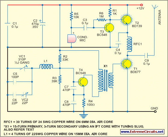
This low-cost short-wave transmitter is tunable from 10 to 15 MHz using a ½J gang condenser VC1, which sets the carrier frequency in conjunction with inductor L1. Frequency trimming is achieved with VC2. The carrier signal is amplified by transistor...
TUNED-COLLECTOR ARMSTRONG OSCILLATOR
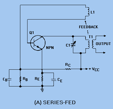
The DC path is established from the negative side (ground) of VCC through RE, Q1, T1, and returns to the positive side of VCC. The figure clearly illustrates that both the AC and DC components flow through the tank circuit....
Low Frequency Antennas
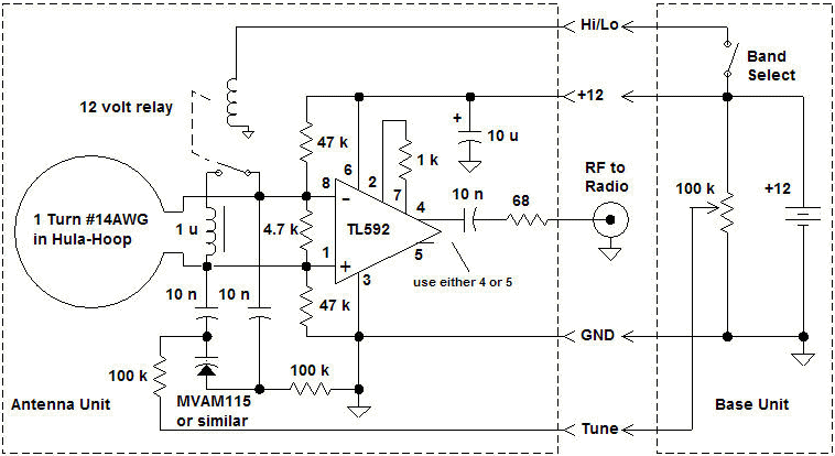
Homemade antennas can significantly enhance the performance of AM and FM radios, short-wave receivers, and scanners. For enthusiasts of talk radio, experimenting with AM band antennas can lead to the ability to receive broadcasts from across the country with surprising...
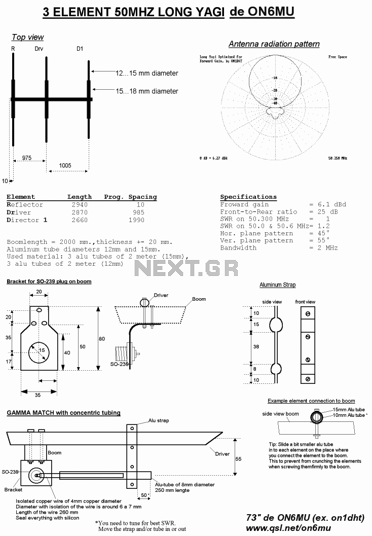
optimized 6 element uhf yagi antenna
The diameter of the antenna elements can range from 5.8 mm, while the dipole diameter can vary from 8 mm to 12 mm, with 12 mm being the recommended size. This adjustment can be made without altering the length or...
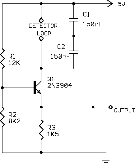
Vehicle Detector
A simple single-transistor Colpitts oscillator is depicted in the schematic. When a vehicle passes over the loop, the inductance decreases, resulting in an increase in the oscillator frequency. A microprocessor measures the oscillator frequency and takes appropriate actions based on...
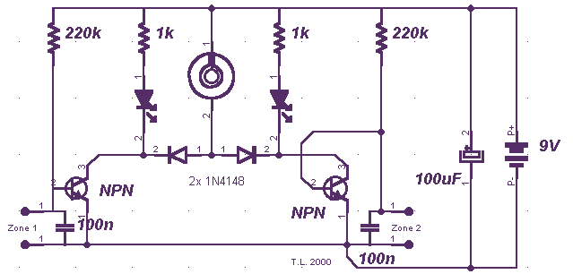
Miniature Loop Alarm
Simple construction, reliable operation, very small power consumption, and, most of all, small size. I started with CMOS logic gates, but was soon forced to abandon the concept after a few unsuccessful (and far too complicated) attempts. Then I suddenly...
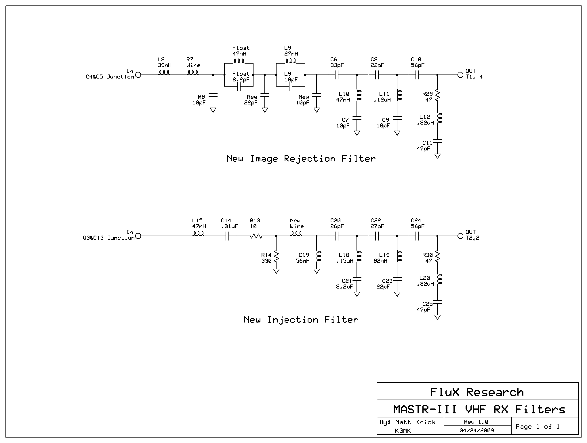
GE/MACOM MASTR-III VHF Station
This article provides conversion instructions for radio model GE/MACOM MASTR-III Group 2 (150.8-174 MHz) Repeater or Base, Combination Number SXS, to enable it to operate effectively in the 144-148 MHz range. It is important to note that this document is...
Rgb-video-amplifier
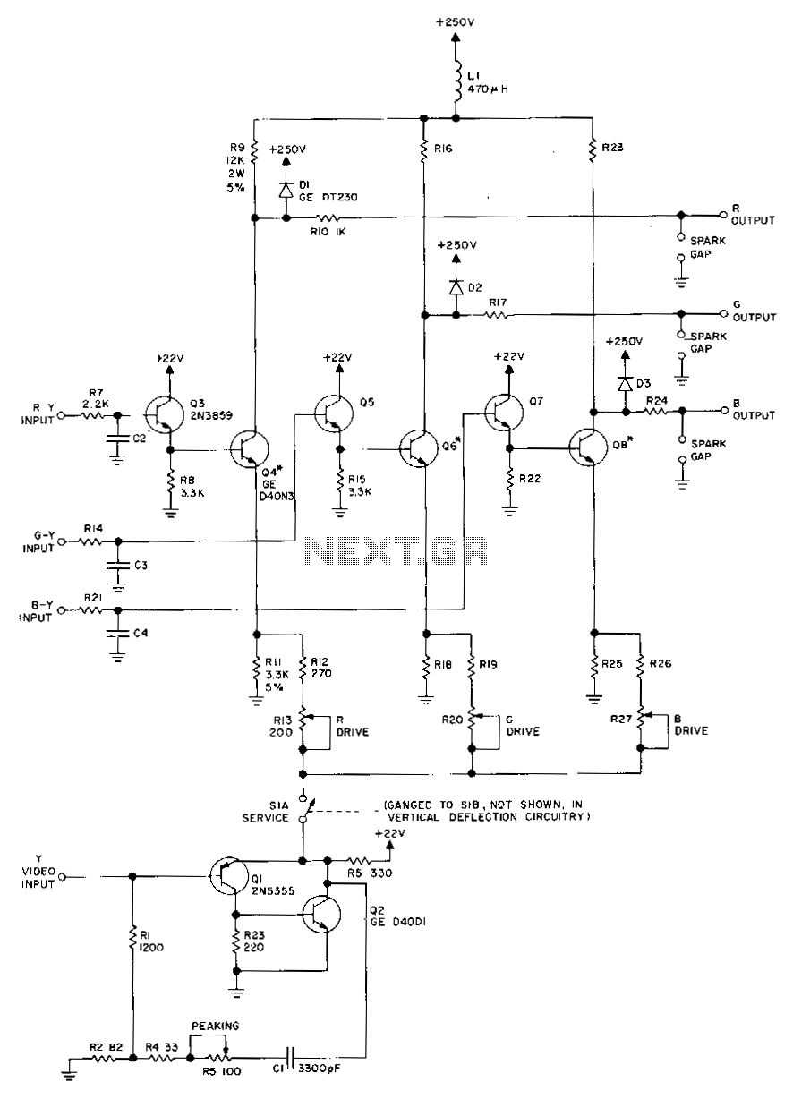
Transistors Q1 and Q2, along with their associated components, provide a low-impedance output necessary for driving the output stages. They enhance gain at high frequencies and improve video peaking for better transient response. Emitter followers Q3, Q5, and Q7 offer...
Dynamic Microphone Preamplifier using C945 transistor
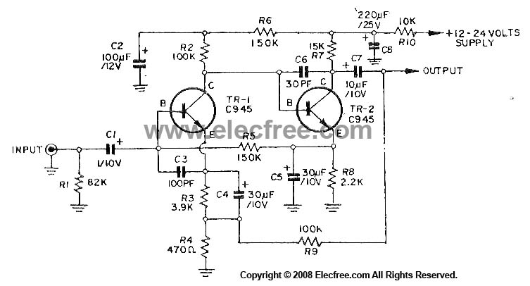
This circuit utilizes three transistors (2SC945, 2C1815, or 2SC828) as the primary components, functioning as a typical low-noise transistor amplifier. It offers a gain of approximately 200 to 300 times and has a frequency response ranging from 50Hz to 100KHz....