


UHF TV Linear Amplifier (450-800MHz)
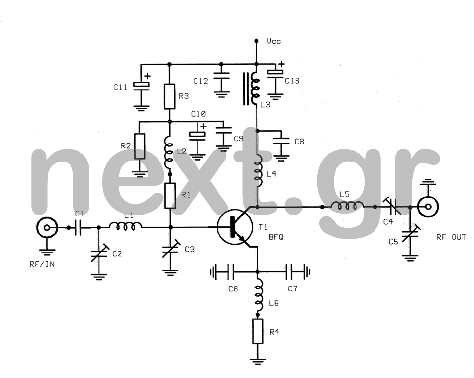
Description: This structure is a radio frequency (RF) amplifier designed for small UHF TV transmitters, operating within the UHF channel range of 450-800 MHz. The amplifier enhances video signals in this frequency range and operates in Class A, utilizing the BFQ68 transistor. Although the construction is relatively simple, it is critical due to the nature of high frequencies. The design features a double-sided printed circuit board (PCB) made from conventional materials, with the exception of two surface-mount capacitors. The choice was made to avoid surface mount technology for easier assembly. The transistor provides a gain of 13 dB at an operating frequency of 800 MHz, with an emitter-collector voltage (Vce) of 15 V and a collector current of 240 mA. When driven with a power of 100 mW, the output power reaches approximately 2 W. Increasing the current to 200 mA allows for an output power of around 3 W, but this may result in a distorted video signal due to intermodulation products and overdriving. The amplifier requires a stabilized power supply capable of delivering 25 V and at least 3 A. The BFQ68 transistor, manufactured by PHILIPS, is intended for applications in central television system amplifiers and low-power TV transmitters. The optimal operating point for the transistor in Class A is a supply voltage of 15 V and a collector current of 250 mA. The transistor comes in a ceramic SOT-122 package. Care should be taken when handling the transistor, as the base is made from beryllium oxide (BeO), which is highly toxic and carcinogenic. Capacitor C1 isolates the input voltage from the driving stage, while two variable capacitors, C2 and C3 (4-30 pF), are used to tune the transistor's input circuit. Output transistor adaptation to a 50 Ω load is achieved through variable capacitors C4 and C5, along with inductor L5. The circuit includes coils to facilitate gain coordination. A biasing circuit is necessary for the Class A operation of the transistor, with the biasing voltage controlled by a 1 kΩ potentiometer. The design incorporates a two-sided PCB layout for component placement, and a photograph of the construction aids in the assembly process. Sufficient cooling is provided by a large heat sink attached to the transistor. The amplifier circuit stabilizes the operating point using resistors R1 = 560 Ω, R2 = 220 Ω, and R3 = 820 Ω, in conjunction with decoupling capacitors to maintain a stable operating voltage of 0.75 V. Inductor L6 consists of ten turns of 0.3 mm wire wound around a 4 mm diameter form, while capacitors C6 and C7 are surface mount, though traditional capacitors can also be used. Coils L1 and L4 are constructed from 1 mm silver wire wrapped around a 4 mm diameter form, and L5 consists of two turns wrapped around the same diameter.
The RF amplifier circuit is designed to operate effectively within the specified frequency range, ensuring minimal signal distortion and optimal performance. The choice of components, particularly the BFQ68 transistor, is crucial for achieving the desired gain and stability. The circuit layout is engineered to minimize parasitic inductance and capacitance, which are critical factors at high frequencies. The use of variable capacitors allows for precise tuning of the input and output stages, facilitating adaptability to different operational conditions.
The power supply requirements are stringent, necessitating a well-regulated 25 V source capable of delivering sufficient current to support the amplifier's operation without introducing noise or fluctuations. This is essential for maintaining the integrity of the amplified video signal. The careful selection of resistors and capacitors for biasing and stabilization ensures that the transistor operates within its optimal parameters, further enhancing performance.
Thermal management is a key consideration in the design, as high-frequency operation can lead to significant heat generation. The inclusion of a robust heat sink is critical to prevent thermal runaway and ensure long-term reliability. The use of beryllium oxide in the transistor's construction poses safety concerns, underscoring the importance of proper handling and disposal practices.
Overall, this RF amplifier circuit represents a well-thought-out approach to enhancing UHF video signals for small TV transmitters, balancing performance with safety and ease of construction. The detailed specifications and design considerations outlined are essential for engineers and technicians involved in the development and implementation of similar RF amplification solutions.This structure is an amplifier RF, covering the range of UHF and intended for small TV transmitters, working in the channel UHF. The amplifier can enhance any video signal to the region UHF (450-800MHz). The circuit operates in class A and uses the known transistor BFQ68. The construction, though simple, we can say that is quite critical, due to the nature of the high frequencies.
The construction is a double-sided printed circuit with conventional materials, although we used only two capacitors surface mount. We preferred not to use it anywhere a surface support, to enable easier the reader to make the construction.
The strengthening of the transistor is 13dB, for an operating frequency of 800MHz, voltage emitter and collector Vce = 15n and current func tioning 240mA. If you give him a driving force 100mW, then the output will providing a power of about 2W. If you give him 200mA, it will take about 3W. The increase in output does not mean that will devote time and clean video signal Video. The output will be distorted, full of lines, no color and unclear. This problem is created because of intermodulation derivatives of the transistor and overdriving. The transistor to work, needs, and any construction, a stabilized power supply with very good stabilizing output voltage of 25V and can supply at least 3A. Transistor BFQ68 manufactured by PHILIPS intended for applications amplifiers central television systems, average power.
At the same time, it is very likely video output stages for low-power television transmitters or driving. The most effective point of the transistor class A is the 15v supply voltage and collector current 250mA.
The transistor is available in ceramic shell SOT-122. If for any reason, the transistor is wrong with some damage, should not be abused, like any other. The base, consisting of beryllium oxide (BeO), a substance extremely toxic and carcinogenic. The capacitor C1 is used to isolate input voltage from the driving stage, and there are still two variables capacitors, C2-C3 (4-30pF) to coordinate the input circuit of the transistor. The adaptation of the transistors in row output of the 50R, made with the help of variables C4 and C5 and inductor L5.
In the circuit we have chosen to build coils to make it easier to coordinate the strengthening step. The transistor, to work on class A, need an extra circuit for biasing the base. The polarization voltage is governed by the potentiometer, which has a value of 1 KO. In the circuit shown the necessary two-sided printed circuit, which will place the materials. The photograph of the construction will help you in how to mount the material on the circuit, since the placement of the material is the "air". The transistors have a large heat sink to cool sufficiently. The circuit of the amplifier to stabilize operating point, needs a panel, consisting of the resistors R1 = 560 R2 = 220 R3 = 820.
To network. This, together with the decoupling capacitors, to stabilize the operating point of the transistor to 0,75 V. Inductor L6 is Ten spirals wire 0,3 mm, wrapped in diameter 4mm, and the two capacitors C6 and C7 are surface mount, without this means that their position can not be used classical capacitors, the same price of course.
The coils L1 and L4 consists of a coil, wrapped in diameter 4mm, with wire 1 mm, silver. To L5 consists of 2 spirals, wrapped in diameter 4mm.
The RF amplifier circuit is designed to operate effectively within the specified frequency range, ensuring minimal signal distortion and optimal performance. The choice of components, particularly the BFQ68 transistor, is crucial for achieving the desired gain and stability. The circuit layout is engineered to minimize parasitic inductance and capacitance, which are critical factors at high frequencies. The use of variable capacitors allows for precise tuning of the input and output stages, facilitating adaptability to different operational conditions.
The power supply requirements are stringent, necessitating a well-regulated 25 V source capable of delivering sufficient current to support the amplifier's operation without introducing noise or fluctuations. This is essential for maintaining the integrity of the amplified video signal. The careful selection of resistors and capacitors for biasing and stabilization ensures that the transistor operates within its optimal parameters, further enhancing performance.
Thermal management is a key consideration in the design, as high-frequency operation can lead to significant heat generation. The inclusion of a robust heat sink is critical to prevent thermal runaway and ensure long-term reliability. The use of beryllium oxide in the transistor's construction poses safety concerns, underscoring the importance of proper handling and disposal practices.
Overall, this RF amplifier circuit represents a well-thought-out approach to enhancing UHF video signals for small TV transmitters, balancing performance with safety and ease of construction. The detailed specifications and design considerations outlined are essential for engineers and technicians involved in the development and implementation of similar RF amplification solutions.This structure is an amplifier RF, covering the range of UHF and intended for small TV transmitters, working in the channel UHF. The amplifier can enhance any video signal to the region UHF (450-800MHz). The circuit operates in class A and uses the known transistor BFQ68. The construction, though simple, we can say that is quite critical, due to the nature of the high frequencies.
The construction is a double-sided printed circuit with conventional materials, although we used only two capacitors surface mount. We preferred not to use it anywhere a surface support, to enable easier the reader to make the construction.
The strengthening of the transistor is 13dB, for an operating frequency of 800MHz, voltage emitter and collector Vce = 15n and current func tioning 240mA. If you give him a driving force 100mW, then the output will providing a power of about 2W. If you give him 200mA, it will take about 3W. The increase in output does not mean that will devote time and clean video signal Video. The output will be distorted, full of lines, no color and unclear. This problem is created because of intermodulation derivatives of the transistor and overdriving. The transistor to work, needs, and any construction, a stabilized power supply with very good stabilizing output voltage of 25V and can supply at least 3A. Transistor BFQ68 manufactured by PHILIPS intended for applications amplifiers central television systems, average power.
At the same time, it is very likely video output stages for low-power television transmitters or driving. The most effective point of the transistor class A is the 15v supply voltage and collector current 250mA.
The transistor is available in ceramic shell SOT-122. If for any reason, the transistor is wrong with some damage, should not be abused, like any other. The base, consisting of beryllium oxide (BeO), a substance extremely toxic and carcinogenic. The capacitor C1 is used to isolate input voltage from the driving stage, and there are still two variables capacitors, C2-C3 (4-30pF) to coordinate the input circuit of the transistor. The adaptation of the transistors in row output of the 50R, made with the help of variables C4 and C5 and inductor L5.
In the circuit we have chosen to build coils to make it easier to coordinate the strengthening step. The transistor, to work on class A, need an extra circuit for biasing the base. The polarization voltage is governed by the potentiometer, which has a value of 1 KO. In the circuit shown the necessary two-sided printed circuit, which will place the materials. The photograph of the construction will help you in how to mount the material on the circuit, since the placement of the material is the "air". The transistors have a large heat sink to cool sufficiently. The circuit of the amplifier to stabilize operating point, needs a panel, consisting of the resistors R1 = 560 R2 = 220 R3 = 820.
To network. This, together with the decoupling capacitors, to stabilize the operating point of the transistor to 0,75 V. Inductor L6 is Ten spirals wire 0,3 mm, wrapped in diameter 4mm, and the two capacitors C6 and C7 are surface mount, without this means that their position can not be used classical capacitors, the same price of course.
The coils L1 and L4 consists of a coil, wrapped in diameter 4mm, with wire 1 mm, silver. To L5 consists of 2 spirals, wrapped in diameter 4mm.
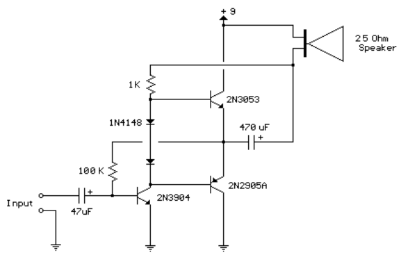
3 transistor audio amp 80 milliwatt
This circuit is similar to the previous one but employs positive feedback to enhance the amplitude delivered to the speaker. It was derived from a small 5-transistor radio utilizing a 25-ohm speaker. In the previous circuit, the load resistor for...
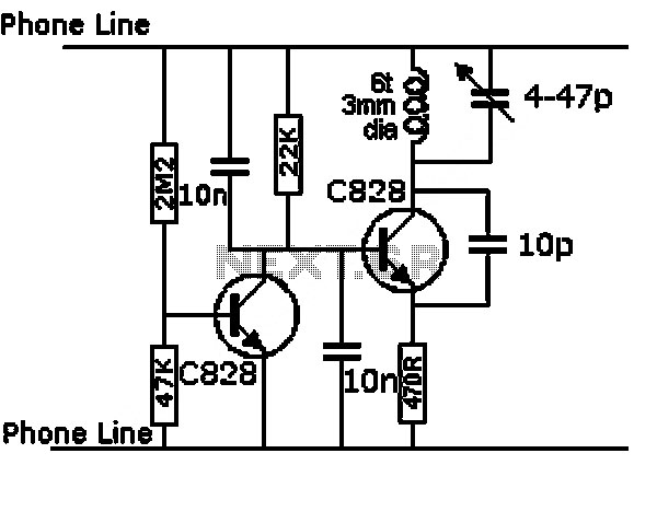
uhf tv transmitter circuit
This is a design circuit for a UHF transmitter. The TV transmitter operates within the UHF frequency range of 470-580 MHz, specifically on channels 21-34. It can transmit signals over distances of 30-100 meters using a cable length of 10-20...
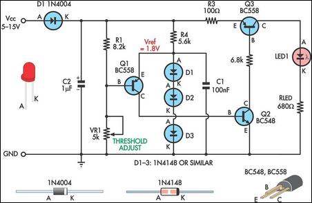
Low Supply Rail Detection
This is a simple low supply rail detection circuit that is inexpensive and can be assembled in approximately 20 minutes. Its low power consumption makes it suitable for integration into battery-powered devices. Instead of utilizing an operational amplifier, the circuit...
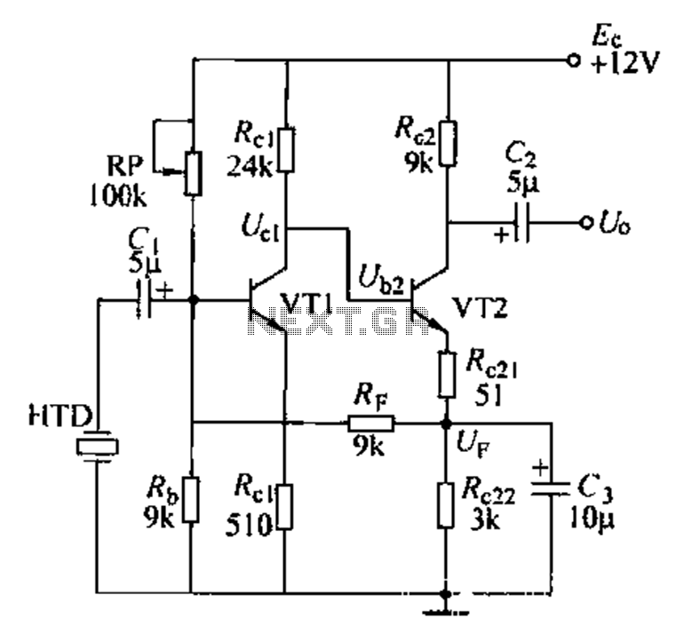
Voice amplifier transistor
Dctl is a two-stage amplifier, with the first stage amplifying the collector voltage of transistor VT1. The second stage, represented by VT2, is proportional to the current flowing through the winding. The RF signal is applied to the sub-base of...
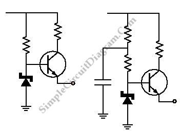
Transistor Buffer for Zener Diode Voltage Regulator
Buffering for the zener diode is achieved through the impedance matching and current amplifying features of the emitter follower, which draws less current from the zener.
Buffering in electronic circuits is essential for ensuring that the performance of one component does...
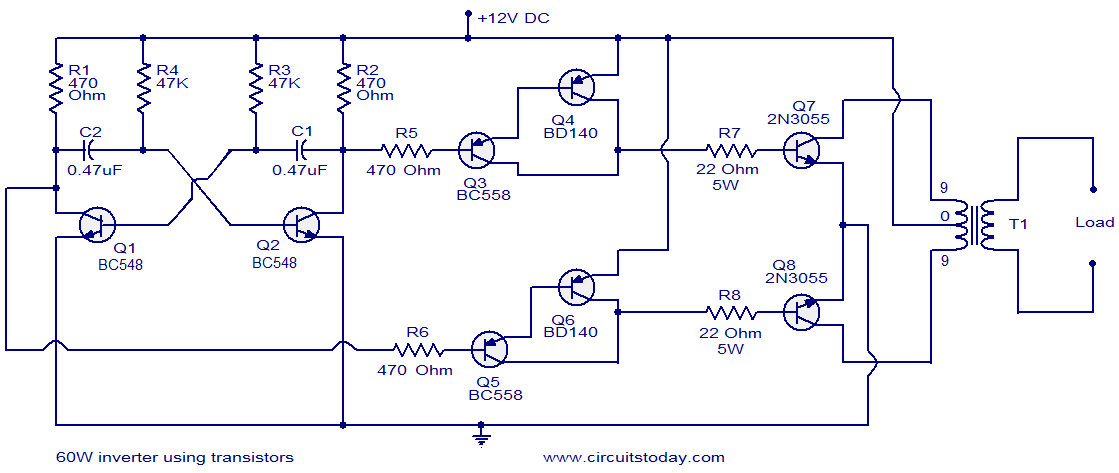
60W inverter using transistors
This circuit diagram illustrates a fully transistorized inverter capable of driving loads of up to 60W. Transistors Q1 and Q2 create a 50Hz astable multivibrator. The output from the collector of Q2 connects to the input of a Darlington pair...
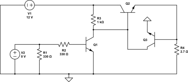
voltage transistor loop to limit the current
The second transistor (T2) is activated by the current passing through the resistor (R1). When a DALI slave unit is connected, this current matches the current flowing through the power transistor (T1). The resistor's value is selected so that when...
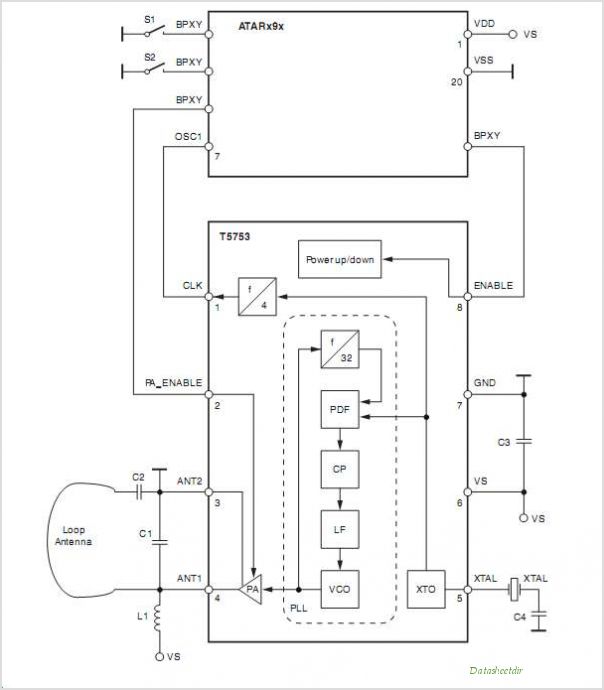
T5753 T5753 UHF ASK/FSK Transmitter
A typical low-cost FSK modulator, TA0038, is implemented by injecting the modulation voltage into the phase-locked loop (PLL) of the carrier synthesizer. This can be achieved in two ways: by summing the modulation voltage with the loop error voltage and...
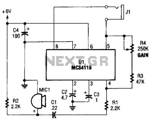
Bird Feeder Monitor Circuit
The first amplifier circuit is a bird phone. In this circuit, the electret microphone (MIC1) is mounted in the neck of a large plastic funnel. The amplifier, built around an MC34119, is then placed outside of the funnel with the...