


Vacuum Tube 80-40M Transmitter Circuit
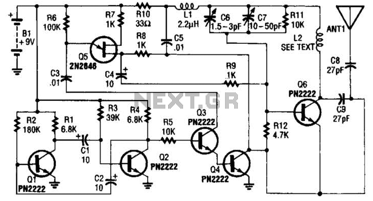
Description: The transmitter utilizes a 6BW6 vacuum tube to achieve an output power of approximately 5 watts. The circuit includes a component CI that is calibrated to produce the cleanest continuous wave (CW) note. The tuning capacitors C8 and C9 have values of 365 pF and dual-365 pF (connected in parallel). The inductor LI consists of 35 turns of #24 enamelled wire wound on a 1-inch plastic tube. FT-243 crystals are employed for operation at frequencies of either 3.5 MHz or 7 MHz. It is important to note that this circuit is not designed to generate a 7-MHz output from a 3.5-MHz crystal, as it does not support frequency doubling.
The transmitter circuit is designed around the 6BW6 vacuum tube, which is known for its efficiency and reliability in RF applications. The output stage, powered by the 6BW6, is capable of delivering a stable output of around 5 watts, making it suitable for low-power transmission applications. The component CI, which is likely a variable capacitor or an inductor, plays a crucial role in tuning the circuit to achieve the clearest possible CW signal.
The tuning capacitors C8 and C9 are critical for frequency selection and stability. The use of a dual-365 pF capacitor in parallel with a single 365 pF capacitor allows for fine-tuning and provides a greater range of capacitance, which is essential for achieving precise frequency adjustments. The inductor LI, constructed from 35 turns of #24 enamelled wire on a 1-inch plastic tube, forms a resonant circuit with the tuning capacitors, enabling effective filtering and signal generation at the desired operating frequency.
The choice of FT-243 crystals for 3.5 MHz or 7 MHz operation provides a reliable frequency reference for the transmitter. However, it is imperative to adhere to the design specifications, as the circuit is not intended for frequency multiplication. Attempting to use a 3.5 MHz crystal to generate a 7 MHz output could lead to undesirable performance and potentially damage the circuit components. Proper selection and installation of the crystals are essential for optimal operation and signal integrity. Using a 6BW6 vacuum tube, the above transmitter delivers about 5 W output. CI is adjusted for cleanest CW note. C8 and C9 are 365 pF and dual-365 pF (paralleled) tuning capacitors. LI is 35 turns of #24 enamelled wire on a 1 plastic tube. FT-243 crystals for 3.5 or 7 MHz are used. Do not use this circuit to produce a 7-MHz output from a 3.5-MHz crystalit is not intended to double over crystal frequencies.
The transmitter circuit is designed around the 6BW6 vacuum tube, which is known for its efficiency and reliability in RF applications. The output stage, powered by the 6BW6, is capable of delivering a stable output of around 5 watts, making it suitable for low-power transmission applications. The component CI, which is likely a variable capacitor or an inductor, plays a crucial role in tuning the circuit to achieve the clearest possible CW signal.
The tuning capacitors C8 and C9 are critical for frequency selection and stability. The use of a dual-365 pF capacitor in parallel with a single 365 pF capacitor allows for fine-tuning and provides a greater range of capacitance, which is essential for achieving precise frequency adjustments. The inductor LI, constructed from 35 turns of #24 enamelled wire on a 1-inch plastic tube, forms a resonant circuit with the tuning capacitors, enabling effective filtering and signal generation at the desired operating frequency.
The choice of FT-243 crystals for 3.5 MHz or 7 MHz operation provides a reliable frequency reference for the transmitter. However, it is imperative to adhere to the design specifications, as the circuit is not intended for frequency multiplication. Attempting to use a 3.5 MHz crystal to generate a 7 MHz output could lead to undesirable performance and potentially damage the circuit components. Proper selection and installation of the crystals are essential for optimal operation and signal integrity. Using a 6BW6 vacuum tube, the above transmitter delivers about 5 W output. CI is adjusted for cleanest CW note. C8 and C9 are 365 pF and dual-365 pF (paralleled) tuning capacitors. LI is 35 turns of #24 enamelled wire on a 1 plastic tube. FT-243 crystals for 3.5 or 7 MHz are used. Do not use this circuit to produce a 7-MHz output from a 3.5-MHz crystalit is not intended to double over crystal frequencies.
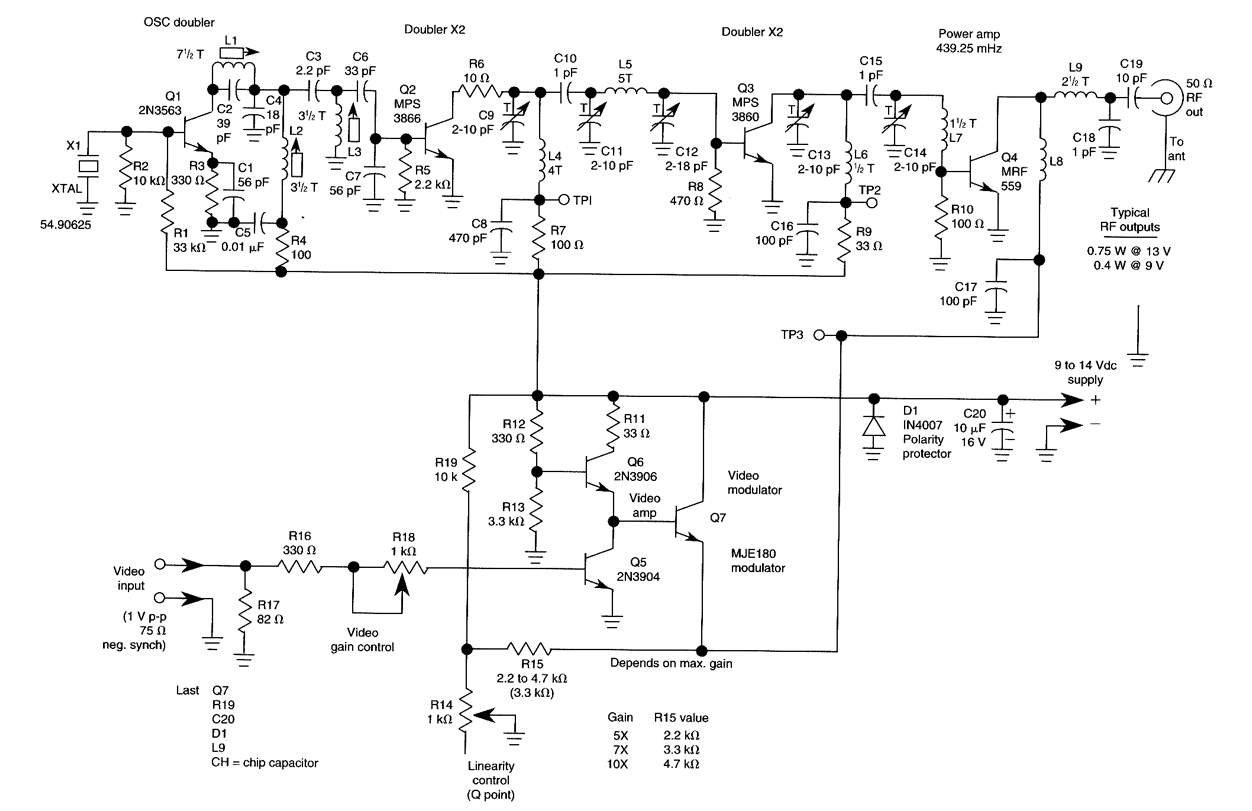
ATV JR TRANSMITTER 440 MHz
This low-power video transmitter is suitable for remote control applications, surveillance, or amateur radio. It employs seven transistors within a crystal oscillator multiplier RF power amplifier chain, along with a high-level video modulator. A supply voltage ranging from 9 to...
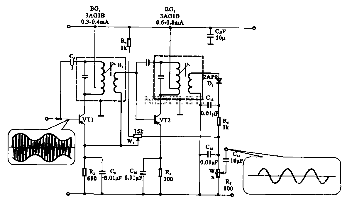
Radio harmonic detection circuit
The demodulation and detection circuit is a radio AM intermediate frequency (IF) signal amplifier that performs two-stage detection using diode Dr. It extracts the audio signal from the IF carrier detection and subsequently sends it to the power amplifier stage....
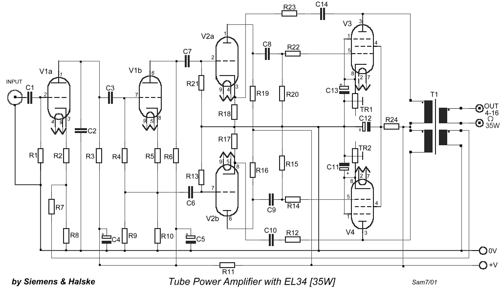
35 Watts Vacuum Tube Power Amplifier by E80CC and EL34
The circuit is designed to create a power amplifier that utilizes E80CC and EL34 vacuum tubes to achieve optimal performance, providing an output of 35 Watts.
The power amplifier circuit employs E80CC and EL34 vacuum tubes, which are known for their...
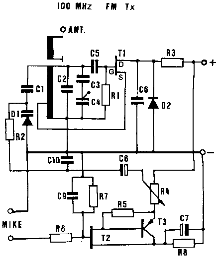
Small Radio Transmitters
Information about building a small radio transmitter, which has a PCB measuring 1.75" x 2.5" (45mm x 68mm) and has a range of approximately 30 yards. The documentation states that the frequency range is 100-108 MHz, but it has been...
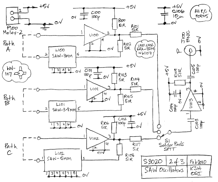
Test Transmitter
The Test Transmitter (A3020) is a combination of three circuits designed to test the Subcutaneous Transmitter (A3019) and to analyze surface acoustic wave (SAW) voltage-controlled oscillators (VCOs). The A3020 incorporates the complete A3019 circuit in its central section, which closely...
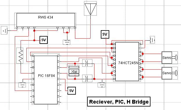
rf modem robotics project using pic16f84 microcontroller
RF technology is an exciting field to incorporate into electronic designs. However, for beginners, constructing reliable RF transmitters and receivers can be challenging.
RF (Radio Frequency) technology plays a crucial role in modern communication systems, enabling wireless data transmission over various...
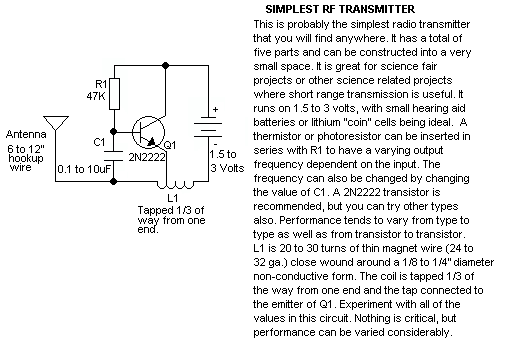
Simple RF Transmitter
This schematic represents a tone transmitter. When using sufficiently small resistor values, it generates a tone. A resistive microphone (such as a carbon microphone) can be placed in parallel with or replace the resistor, allowing modulation of the tone frequency...
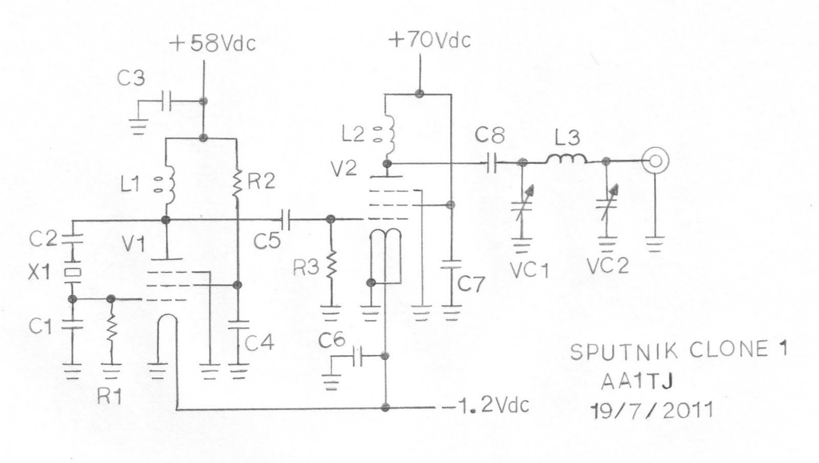
Sputnik QSO Party Transmitter Prototype
This document describes a prototype transmitter for the Sputnik QSO Party. The RF output power is 450 mW, with 70 V DC at 14.4 mA on the V2 anode. The screen current (G2) for V2 is 1.6 mA, while the...
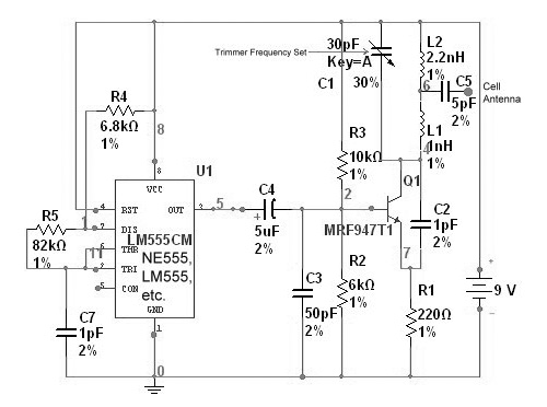
radio station blocker circuit
This device functions as a reversal of a radio station, sending a null signal to a selected frequency to eliminate the actual broadcast. The radio transmitter operates at a loss of 10,000W; therefore, this circuit is intended for use only...