


Vlf/Vhf Wideband Low-Noise Active Antenna Circuit
#active antenna
#low-noise
#wideband
#MOSFET
#VHF
#VLF
#receiver
#RF amplifier
#high gain
#whip antenna
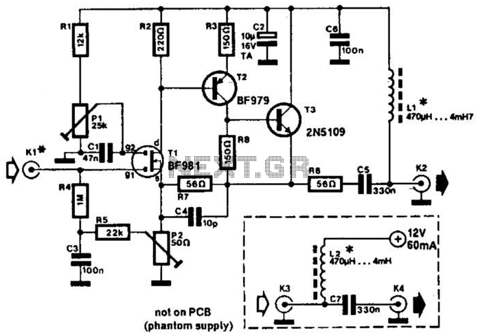
Description: A 30- to 50-cm whip antenna provides reception from 10 kHz to over 220 MHz. Tl, a dual-gate MOSFET, provides low noise, high-input impedance, and high gain. The circuit is powered via the coaxial cable used to connect the antenna to a receiver.
The described circuit employs a whip antenna, which is a versatile and compact design suitable for a wide range of frequencies, specifically from 10 kHz to over 220 MHz. This frequency range makes it particularly effective for applications in both the AM and FM bands, as well as for various shortwave communications.
The use of a dual-gate MOSFET (Tl) in the circuit is noteworthy due to its advantageous characteristics. This type of MOSFET is particularly beneficial for radio frequency applications because it offers low noise figures, which is critical for maintaining signal integrity and improving overall reception quality. Additionally, the high-input impedance of the MOSFET minimizes the loading effect on the antenna, thereby allowing it to operate efficiently across the specified frequency range. The high gain provided by the dual-gate configuration enhances the signal strength received from the antenna, making it suitable for weak signal detection.
Powering the circuit through the coaxial cable is a practical design choice. This method allows for a simplified setup, eliminating the need for a separate power source. The coaxial cable not only transmits the RF signal to the receiver but also supplies the necessary voltage to operate the MOSFET. This dual functionality is particularly advantageous in reducing the complexity of the overall system and ensuring that the antenna remains compact and easy to deploy.
In summary, the combination of a whip antenna, a dual-gate MOSFET, and the coaxial cable power supply creates an efficient and effective RF reception circuit, suitable for a variety of applications in the radio frequency spectrum. The design emphasizes low noise, high gain, and ease of integration, making it a valuable choice for enthusiasts and professionals alike in the field of electronics and communications. A 30- to 50-cm whip antenna provides reception from 10 kHz to over 220 MHz. Tl, a dual-gate MOSFET, provides low noise, high-input impedance, and high gain, The circuit is powered via the coaxial cable used to connect the antenna to a receiver.
The described circuit employs a whip antenna, which is a versatile and compact design suitable for a wide range of frequencies, specifically from 10 kHz to over 220 MHz. This frequency range makes it particularly effective for applications in both the AM and FM bands, as well as for various shortwave communications.
The use of a dual-gate MOSFET (Tl) in the circuit is noteworthy due to its advantageous characteristics. This type of MOSFET is particularly beneficial for radio frequency applications because it offers low noise figures, which is critical for maintaining signal integrity and improving overall reception quality. Additionally, the high-input impedance of the MOSFET minimizes the loading effect on the antenna, thereby allowing it to operate efficiently across the specified frequency range. The high gain provided by the dual-gate configuration enhances the signal strength received from the antenna, making it suitable for weak signal detection.
Powering the circuit through the coaxial cable is a practical design choice. This method allows for a simplified setup, eliminating the need for a separate power source. The coaxial cable not only transmits the RF signal to the receiver but also supplies the necessary voltage to operate the MOSFET. This dual functionality is particularly advantageous in reducing the complexity of the overall system and ensuring that the antenna remains compact and easy to deploy.
In summary, the combination of a whip antenna, a dual-gate MOSFET, and the coaxial cable power supply creates an efficient and effective RF reception circuit, suitable for a variety of applications in the radio frequency spectrum. The design emphasizes low noise, high gain, and ease of integration, making it a valuable choice for enthusiasts and professionals alike in the field of electronics and communications. A 30- to 50-cm whip antenna provides reception from 10 kHz to over 220 MHz. Tl, a dual-gate MOSFET, provides low noise, high-input impedance, and high gain, The circuit is powered via the coaxial cable used to connect the antenna to a receiver.
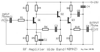
40mhz rf amplifier circuit
This is a 40 MHz RF amplifier circuit. The sensitivity of a receiver can be significantly enhanced by integrating this circuit between the receiver and the antenna. The amplifier does not utilize resonant circuits and is suitable for both medium...
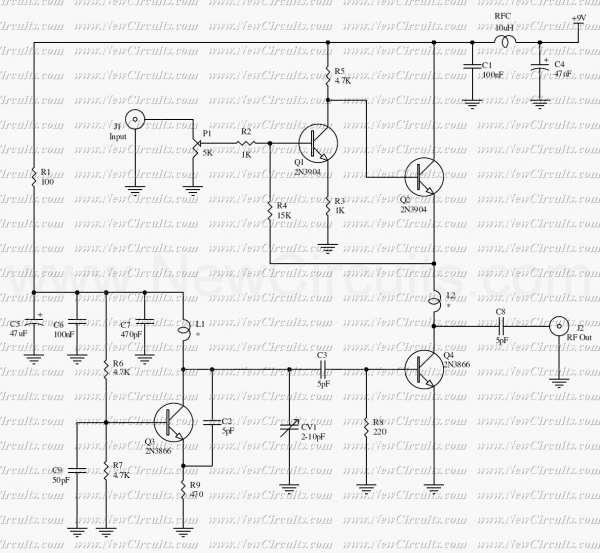
VHF Video Sender/Transmitter
This circuit is a powerful video sender in VHF band. The modulator section is designed to operate on either channels 7 to 13 or 14 to 29. For channels 7 to 13, L1 and L2 are 3 turns of #22...
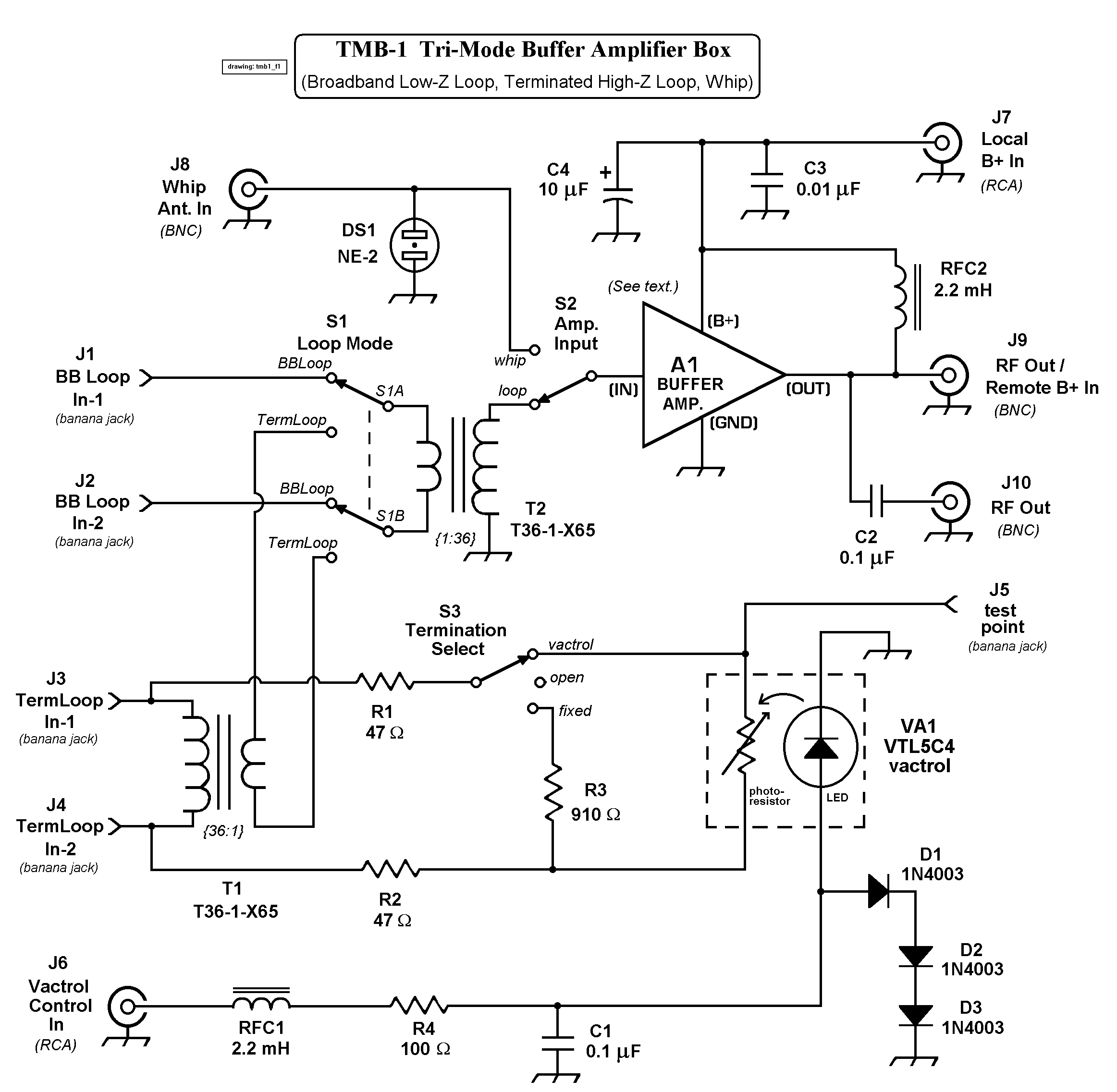
TMB-1 Tri-Mode Buffer Amplifier Box
The TMB-1 is an RF amplifier unit and receiving accessory compatible with low-impedance broadband loops, high-impedance terminated loops (such as Pennant, Flag, or Kaz Delta), and whip (telescoping rod) antennas. This design is optimized for operation within the frequency range...
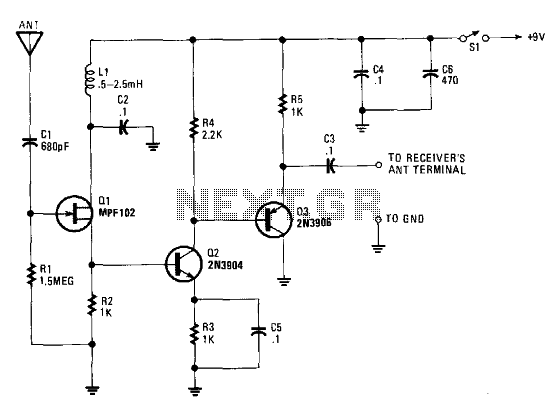
Active Antenna With Gain
The signal booster, constructed using several transistors and supporting components, provides an RF gain ranging from approximately 12 to 18 dB across a frequency range of about 100 kHz to over 30 MHz. The RF signal is directly coupled from...
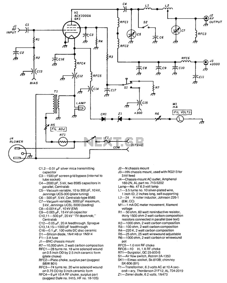
1 500-W Rf Amplifier
The frequency range of this amplifier is 1.8 to 54 MHz. The required RF drive for full output is approximately 30 W. The grid compartment (Rl, R2, RFC4, RFC5) must be shielded from other circuitry, particularly the output circuitry. Capacitors...
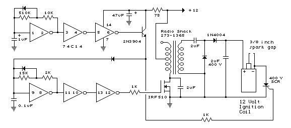
MOSFET IRF510 Capacitor Discharge Ignition(CDI) Circuit and explanation
A 2 µF capacitor is charged to approximately 340 volts, and the discharge is controlled by a silicon-controlled rectifier (SCR). A Schmitt trigger oscillator (74C14) and a MOSFET (IRF510) are utilized to drive the low-voltage side of a small (120/12...
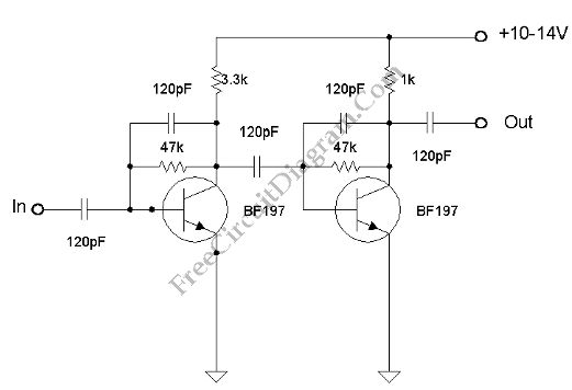
VHF-UHF Antenna Amplifier (Booster) 40-500MHz
This amplifier has VHF (very high frequency) and UHF (ultra high frequency) response, and it can be used as a receiver booster, for example. Here is the schematic.
The described amplifier is designed to enhance signal reception in the VHF and...
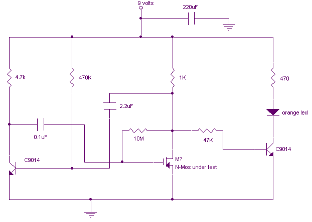
MOSFET Tester circuit
This is a variation on the astable multivibrator. Circuit was recently developed to test for N-mosfets (the power kind e.g. irf830). I don't claim circuit can test all bad mosfets or all fault mosfet conditions. If mosfet is working it...
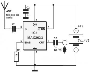
vhf rf preamp 100 175 mhz with max2633
This diagram represents a VHF RF preamplifier circuit operating within the frequency range of 100-175 MHz using a single MAX2633 chip. The circuit is suitable for the entire VHF broadcast and PMR band (100-175 MHz) and can be constructed easily...