


Wide band high frequency amplifier circuit
#amplifier
#high frequency
#VHF
#transistor
#signal booster
#FM radio
#amateur radio
#PNP amplifier
#wide band
#75-150 MHz
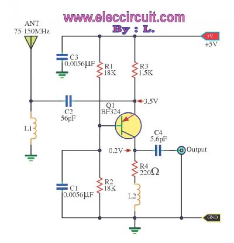
Description: This is a wideband high-frequency amplifier circuit designed for a frequency range between 75-150 MHz. It utilizes a PNP transistor amplifier to enhance signal strength before it reaches the receiver of devices such as phones, FM radios, or amateur radios. The circuit specifically targets high-frequency signals, particularly in the VHF range. The amplifier circuit serves to boost signal strength. The operation involves an inductive antenna connected to the emitter pin of the transistor Q1, which maintains a low output impedance. A 50-ohm antenna can be used with this circuit. The signal at Q1 is amplified and sent to a tuner or receiver.
More: The L1 coil consists of 10 turns of 24 SWG enamel-coated magnet wire with an inside diameter of 3 mm, while the L2 coil has 13 turns of the same wire gauge with an inside diameter of 5 mm. Both coils are air-core types. The power supply for this circuit is +5 V, and it operates at a current of 2.5 mA. When selecting components, it is important to consider the antenna and the design of high-frequency printed circuit boards. The circuit can be assembled onto a universal PCB board, but care should be taken to minimize interference. A basic antenna and reasonable PCB design for high frequency are recommended. The component list includes resistors: R1 and R2 at 18K, R3 at 1.5K, and R4 at 220 ohms. Capacitors include C1 and C3 at 0.0056uF 50V, C2 at 56pF 50V, and C4 at 5.6pF 50V. The semiconductor used is Q1, which is a BF324 PNP transistor.
In this circuit design, the choice of components and their specifications is crucial for optimal performance. The resistors should be rated at ¼ W with a tolerance of +5%. The capacitors must be rated for at least 50V to ensure they can handle the voltage levels in the circuit. The inductive coils, L1 and L2, are integral to the amplifier's functionality, as they help in tuning the circuit to the desired frequency range while providing the necessary impedance matching.
The layout of the printed circuit board (PCB) should be carefully planned to minimize parasitic capacitance and inductance, which can adversely affect the performance of high-frequency circuits. It is advisable to use short traces and proper grounding techniques to reduce noise and improve signal integrity. Additionally, the assembly process should include a thorough inspection to ensure that all components are correctly oriented and soldered to avoid operational issues.
Overall, this wideband high-frequency amplifier circuit is suitable for applications requiring enhanced signal strength in the VHF range, making it an effective solution for various radio communication devices.This is Wide band high frequency amplifier circuit,Wide frequency band between 75-150 MHz,Using transistors, a PNP amplifier.To enhance the signal strength.Before the receiver of the phone. Or FM radio or amateur radio. If high-frequency signals, in particular, its VHF. The booster circuit is one, serves to amplify the signal strength only. Operation of the circuit. High-frequency range VHF, inductive antenna, to the emitter pin of the transistor Q1. so circuit held, in conjunction with the bass, a nice low output impedance. You can use a special access code 50 ohms, the antenna on the circuit at all.Signal at the Q1 will be expanded to increase.And sent to a tuner or receiver to the receiver.
The L1 coil wire enamel No. 24 SWG, thousands of rounds of 10, inside diameter 3 mm. And the coil L2 wire number. Thousands of 13 turns, diameter 5 mm. Stent both as a non-core, or an air core. The power supply is +5 V, this circuit while current is 2.5 mA. If the components to use. Should be based on the antenna. And design of high frequency printed circuit boards as well. How to assemble circuits The assembling circuit onto the universal PCB board as Figure 2 May have problems, the interference inserted come in, If assembly circuit to actually use. Should have a basic antenna and PCB design in high frequency reasonable. The components list Resistors size ¼ W +5% R1, R2__________18K R3_____________1.5K R4_____________220 ohm Capacitors C1, C3__________0.0056uF 50V C2_____________56pF 50V C4_____________5.6pF 50V Semiconductor Q1___________BF324___PNP Transistors Others L1___is 10 turns of 24 SWG enamel coated magnet wire wound with a inside diameter of about 3mm.
no core. L2____is 13 turns of 24 SWG enamel coated magnet wire wound with a inside diameter of about 5 mm. no core.
More: The L1 coil consists of 10 turns of 24 SWG enamel-coated magnet wire with an inside diameter of 3 mm, while the L2 coil has 13 turns of the same wire gauge with an inside diameter of 5 mm. Both coils are air-core types. The power supply for this circuit is +5 V, and it operates at a current of 2.5 mA. When selecting components, it is important to consider the antenna and the design of high-frequency printed circuit boards. The circuit can be assembled onto a universal PCB board, but care should be taken to minimize interference. A basic antenna and reasonable PCB design for high frequency are recommended. The component list includes resistors: R1 and R2 at 18K, R3 at 1.5K, and R4 at 220 ohms. Capacitors include C1 and C3 at 0.0056uF 50V, C2 at 56pF 50V, and C4 at 5.6pF 50V. The semiconductor used is Q1, which is a BF324 PNP transistor.
In this circuit design, the choice of components and their specifications is crucial for optimal performance. The resistors should be rated at ¼ W with a tolerance of +5%. The capacitors must be rated for at least 50V to ensure they can handle the voltage levels in the circuit. The inductive coils, L1 and L2, are integral to the amplifier's functionality, as they help in tuning the circuit to the desired frequency range while providing the necessary impedance matching.
The layout of the printed circuit board (PCB) should be carefully planned to minimize parasitic capacitance and inductance, which can adversely affect the performance of high-frequency circuits. It is advisable to use short traces and proper grounding techniques to reduce noise and improve signal integrity. Additionally, the assembly process should include a thorough inspection to ensure that all components are correctly oriented and soldered to avoid operational issues.
Overall, this wideband high-frequency amplifier circuit is suitable for applications requiring enhanced signal strength in the VHF range, making it an effective solution for various radio communication devices.This is Wide band high frequency amplifier circuit,Wide frequency band between 75-150 MHz,Using transistors, a PNP amplifier.To enhance the signal strength.Before the receiver of the phone. Or FM radio or amateur radio. If high-frequency signals, in particular, its VHF. The booster circuit is one, serves to amplify the signal strength only. Operation of the circuit. High-frequency range VHF, inductive antenna, to the emitter pin of the transistor Q1. so circuit held, in conjunction with the bass, a nice low output impedance. You can use a special access code 50 ohms, the antenna on the circuit at all.Signal at the Q1 will be expanded to increase.And sent to a tuner or receiver to the receiver.
The L1 coil wire enamel No. 24 SWG, thousands of rounds of 10, inside diameter 3 mm. And the coil L2 wire number. Thousands of 13 turns, diameter 5 mm. Stent both as a non-core, or an air core. The power supply is +5 V, this circuit while current is 2.5 mA. If the components to use. Should be based on the antenna. And design of high frequency printed circuit boards as well. How to assemble circuits The assembling circuit onto the universal PCB board as Figure 2 May have problems, the interference inserted come in, If assembly circuit to actually use. Should have a basic antenna and PCB design in high frequency reasonable. The components list Resistors size ¼ W +5% R1, R2__________18K R3_____________1.5K R4_____________220 ohm Capacitors C1, C3__________0.0056uF 50V C2_____________56pF 50V C4_____________5.6pF 50V Semiconductor Q1___________BF324___PNP Transistors Others L1___is 10 turns of 24 SWG enamel coated magnet wire wound with a inside diameter of about 3mm.
no core. L2____is 13 turns of 24 SWG enamel coated magnet wire wound with a inside diameter of about 5 mm. no core.
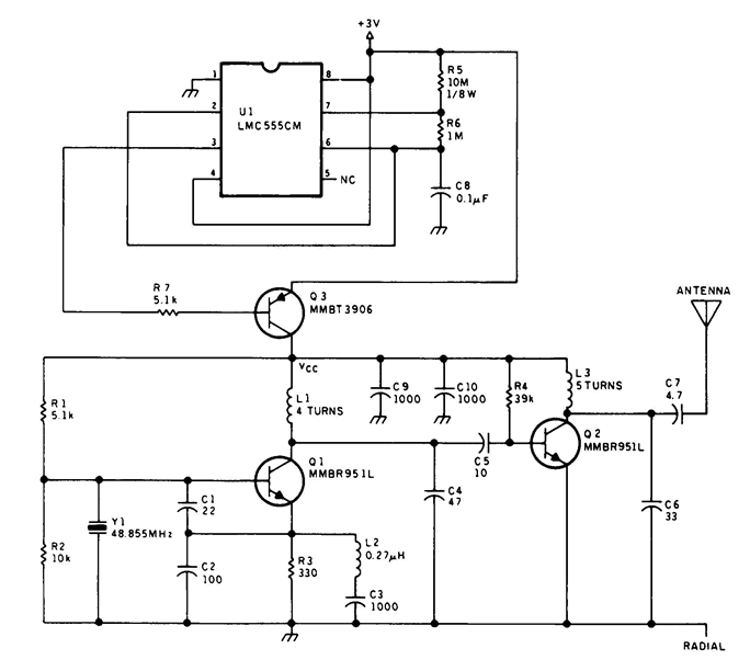
VHF Beacon
The 555 timer oscillator section can be removed and replaced with a preferred microphone modulating circuit to transmit audio to a television set, requiring minimal tuning. The schematics available on Schematics Depot were sourced from the internet and are presumed...
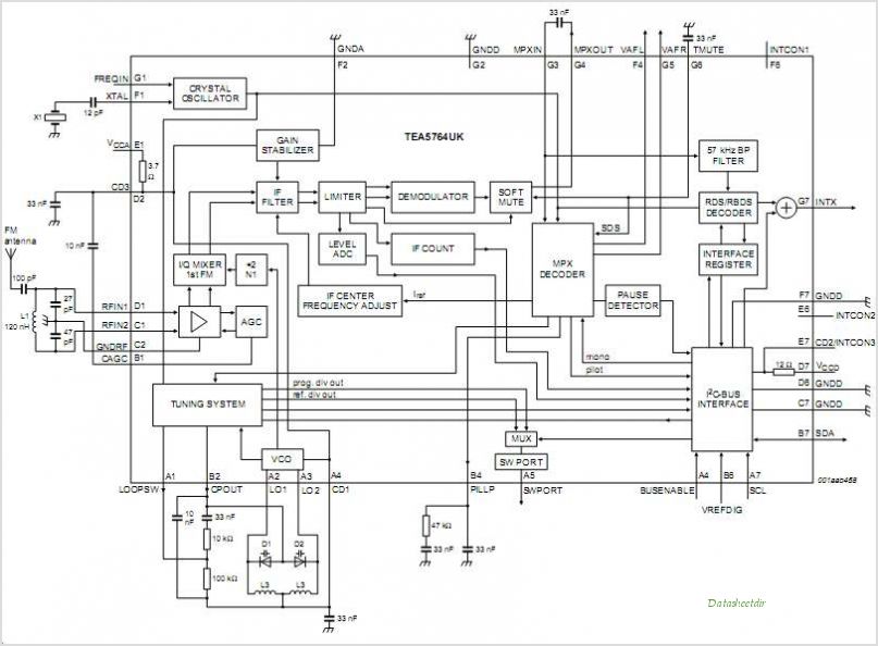
TEA5764UK TEA5764UK FM Radio + RDS
The TK10931V is an intermediate frequency (IF) integrated circuit that incorporates two IF systems—one designated for frequency modulation (FM) and the other for amplitude modulation (AM)—along with a detector. This device is suitable for use in amateur radios, CB radios,...
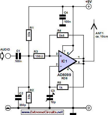
vhf fm transmitter
Integrated circuits (ICs) that were once prohibitively expensive for hobbyists are now more affordably priced. A notable example is the AD8099 from Analog Devices, which is available for a modest cost. The AD8099 is a high-speed operational amplifier (op-amp) with...
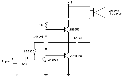
improved 3 transistor audio amp
This circuit is similar to the previous one but employs positive feedback to enhance the amplitude delivered to the speaker. It is adapted from a small 5-transistor radio that utilizes a 25-ohm speaker. In the earlier circuit, the load resistor...
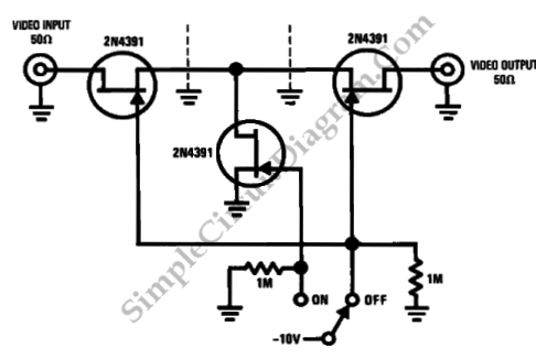
High Frequency Switch
This is a high-frequency switch circuit. This circuit utilizes the 2N4391 transistor. When in the off state, it provides a high off-impedance of less than 0.2 pF and exhibits a low on-resistance.
The high-frequency switch circuit designed with the 2N4391 transistor...
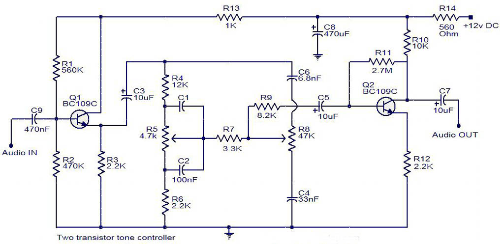
tone controller circuit diagram two transistor
The electrical schematic diagram presented below illustrates a simple two-transistor tone controller audio circuit, which is available for free download. This circuit is based on the well-known Baxandall tone control design. Variations in the values of the transistor components in...
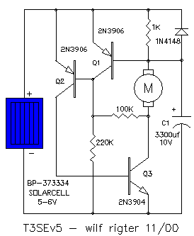
T3SE type 3 SE
The all-transistor T3SE operates similarly to a conventional switch mode power supply (SE). Like the Tritium model, it activates when the charging current falls below a specified threshold. After the circuit is triggered, positive feedback is utilized to latch the...
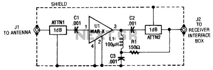
Vhf-Uhf Preamp Circuit
The MAR-x preamplifier is designed to operate within a frequency range of up to 1.5 or 2 GHz, depending on the selected MAR-x integrated circuit (IC). For applications requiring a low noise figure, ATTN1 should be omitted. Both ATTN1 and...
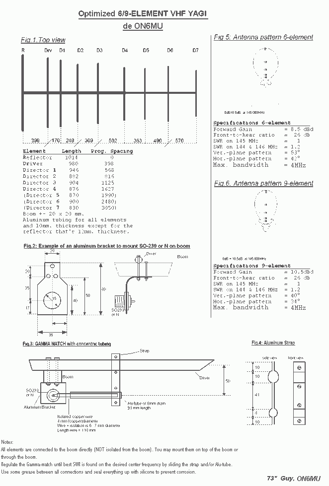
Optimized 6/9 element VHF Yagi Antenna
The computer optimized 9 el. homebrew antenna is performing very well. I have made many long distance contacts using the ON6MU VHF Yagi antenna. I have the antenna located only 35 feet above the ground. More: The very first day...