


433 MHz 4-ch receiver with relay output transmitter
#433 MHz
#receiver
#transmitter
#relay
#RF
#remote control
#wireless
#momentary output
#latch output
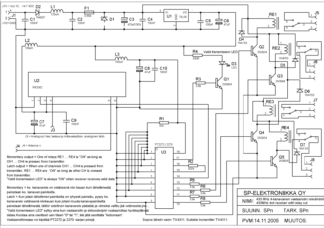
Description: Momentary output: One of the relays RE1...RE4 is ON as long as CH1---CH4 is pressed from transmitter. Latch output: when one of channels CH1...CH4 is pressed from transmitter RE1...RE4 are ON as long as other CH is pressed from transmitter. Valid transmission indicator: LED is always on when receiver receives valid data.
This circuit description pertains to a wireless relay control system utilizing a transmitter and receiver setup. The system features four channels (CH1 to CH4), each corresponding to a relay output (RE1 to RE4).
In the momentary output mode, when a button on the transmitter corresponding to any of the channels (CH1 to CH4) is pressed, the associated relay (RE1 to RE4) activates. This state remains until the button is released, allowing for temporary control over the connected load or device.
The latch output mode allows for a more sustained activation of the relays. When a button on the transmitter is pressed, the corresponding relay is activated and will remain in this state as long as at least one other channel button is held down. This feature enables a more complex control scheme where multiple relays can be activated simultaneously, providing flexibility in controlling multiple devices or systems.
An important aspect of the design is the valid transmission indicator, which is represented by an LED. This LED remains illuminated whenever the receiver successfully receives data from the transmitter, providing a visual confirmation of operational status and aiding in troubleshooting by indicating whether the system is functioning correctly.
Overall, this circuit effectively combines momentary and latch control functionalities while ensuring reliable feedback through the LED indicator, making it suitable for various applications requiring remote relay activation.Momentary output : One of the relays RE1...RE4 is ON as long as CH1---CH4 is pressed from transmitter. Latch output: when one of channels CH1...CH4 is pressed from transmitter RE1...RE4 are ON as long as other CH is pressed from transmitter.
Valid transmission indicator: LED is always on when reciever recieves valid data.
This circuit description pertains to a wireless relay control system utilizing a transmitter and receiver setup. The system features four channels (CH1 to CH4), each corresponding to a relay output (RE1 to RE4).
In the momentary output mode, when a button on the transmitter corresponding to any of the channels (CH1 to CH4) is pressed, the associated relay (RE1 to RE4) activates. This state remains until the button is released, allowing for temporary control over the connected load or device.
The latch output mode allows for a more sustained activation of the relays. When a button on the transmitter is pressed, the corresponding relay is activated and will remain in this state as long as at least one other channel button is held down. This feature enables a more complex control scheme where multiple relays can be activated simultaneously, providing flexibility in controlling multiple devices or systems.
An important aspect of the design is the valid transmission indicator, which is represented by an LED. This LED remains illuminated whenever the receiver successfully receives data from the transmitter, providing a visual confirmation of operational status and aiding in troubleshooting by indicating whether the system is functioning correctly.
Overall, this circuit effectively combines momentary and latch control functionalities while ensuring reliable feedback through the LED indicator, making it suitable for various applications requiring remote relay activation.Momentary output : One of the relays RE1...RE4 is ON as long as CH1---CH4 is pressed from transmitter. Latch output: when one of channels CH1...CH4 is pressed from transmitter RE1...RE4 are ON as long as other CH is pressed from transmitter.
Valid transmission indicator: LED is always on when reciever recieves valid data.
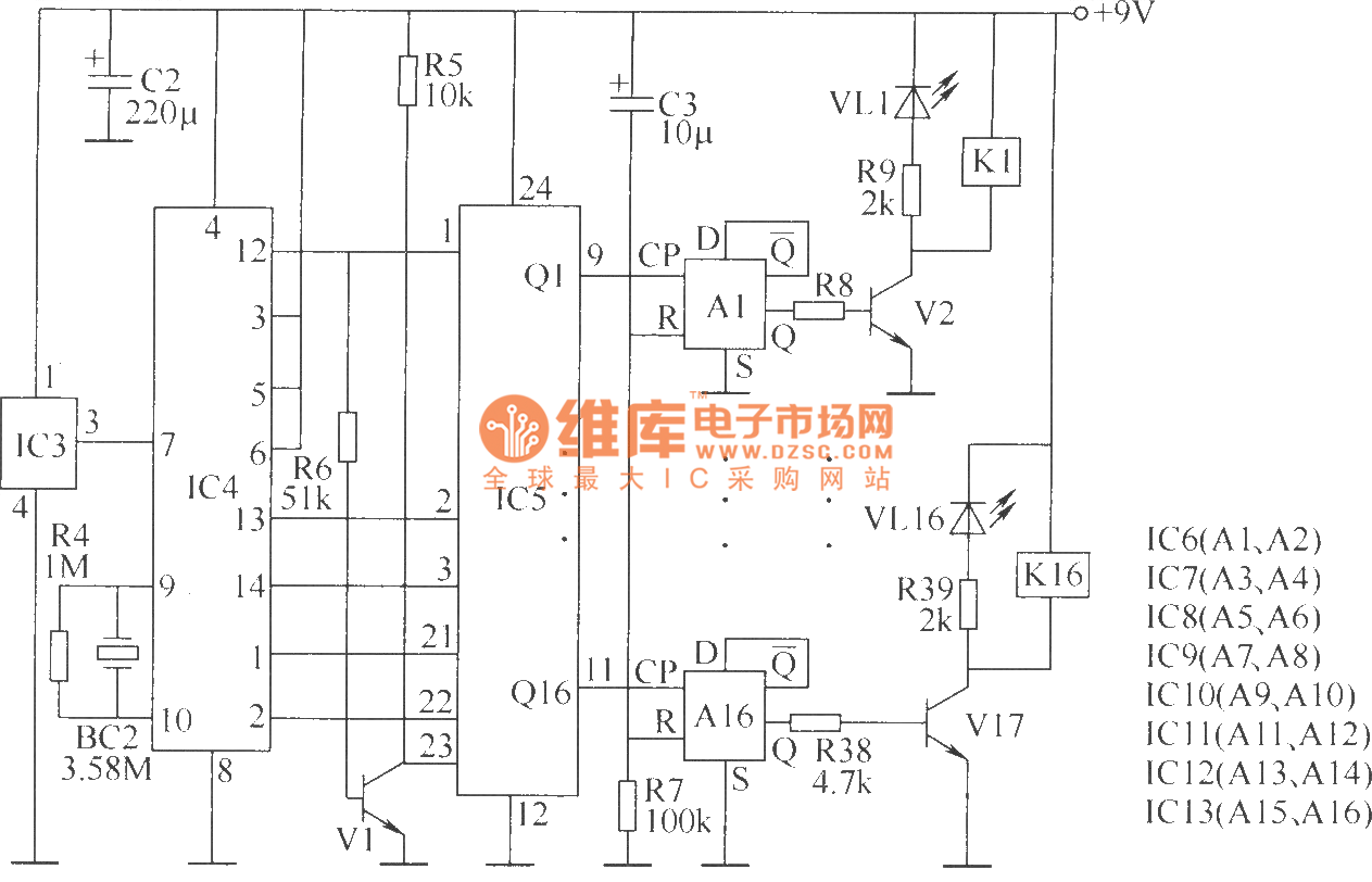
Wireless remote control switch circuit 5
The wireless remote control transmitter circuit consists of control buttons S1 to S16, resistors R1 to R3, a capacitor C1, a regulator diode VS, a crystal oscillator BC1, and DTMF encoder integrated circuits IC1 and IC2. The circuit components are...
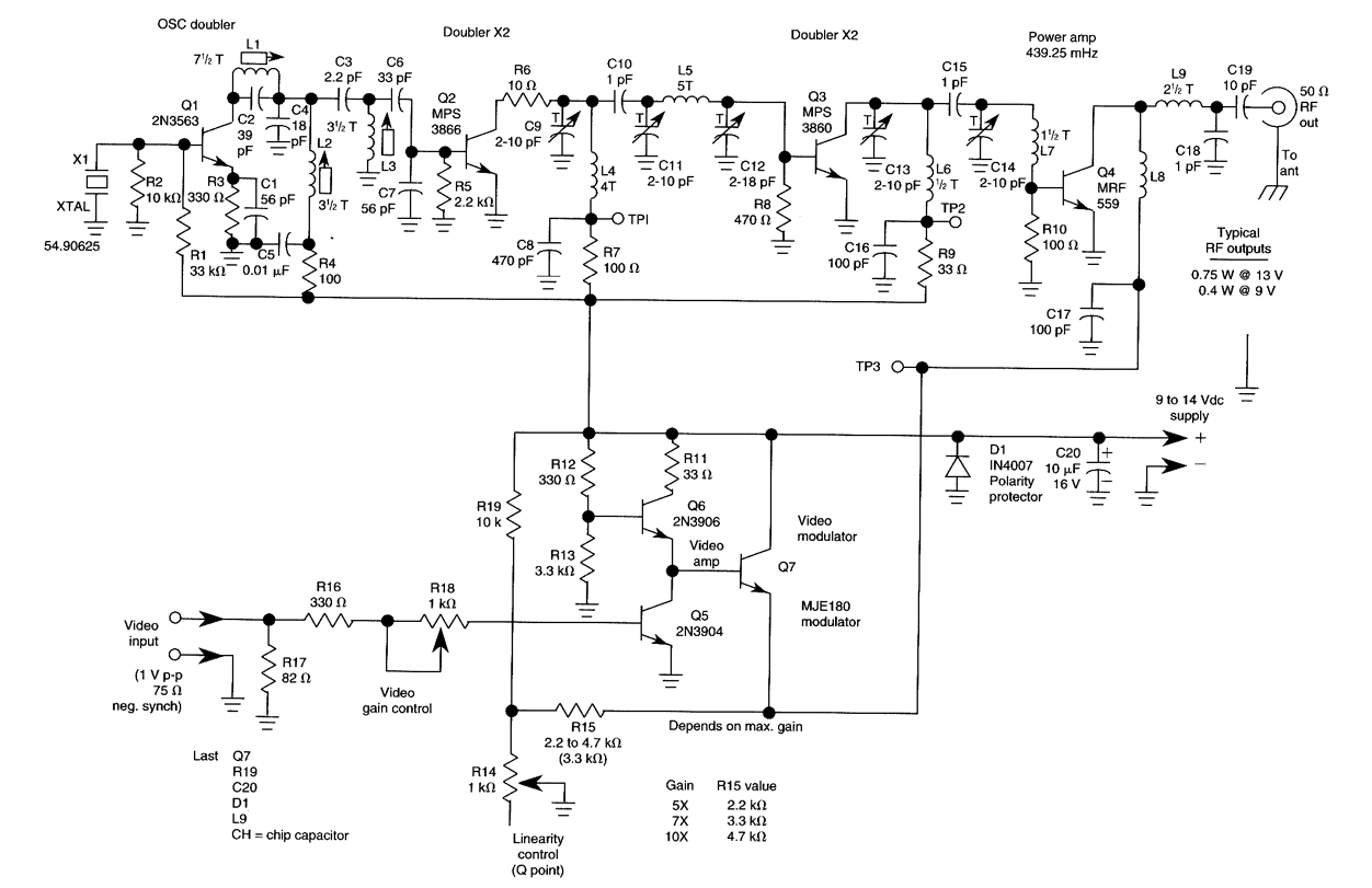
ATV JR TRANSMITTER 440 MHz
This low-power video transmitter is suitable for remote control applications, surveillance, or amateur radio. It employs seven transistors within a crystal oscillator multiplier RF power amplifier chain, along with a high-level video modulator. A supply voltage ranging from 9 to...
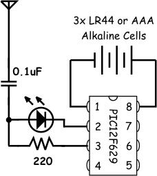
Emergency Egg Locator Beacon (EELB)
This project was inspired by a circuit that a friend, Simon Field, showcased. He built a simple transmitter circuit using a 1 MHz "can" oscillator and a serial connector. In his circuit, he utilized a computer to turn the transmitter...
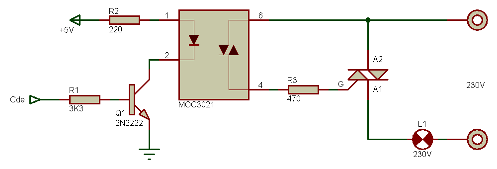
relay triac
The task involves converting a relay in a design to a triac. The circuit switches a 120V nichrome wire with a resistance of 60 ohms. The circuit is powered by a 12V transformer, and there is a 120V neutral and...
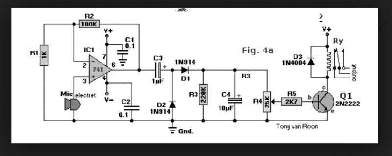
sound activated relay
A circuit that enables control of a relay in response to sound from a non-amplified sound source, such as a computer, CD player, or a Digital Sound Recorder board. This circuit accepts audio input from any non-amplified sound source, and...
RF field strength meter
A simple Field Strength Meter consists of a small antenna, a detector diode, a resistor, a capacitor, and a micro ammeter. This circuit is sensitive enough to detect HF fields when positioned close to the transmitting antenna. The circuit functioned...
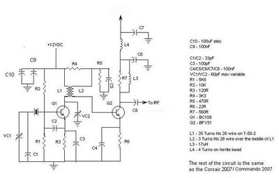
Corsair and Commando TXs
This document provides information about the Corsair and Commando Transmitters designed by Dave Martin of WNKR. It outlines the construction of each transmitter and includes examples created by others. The circuit diagram presented illustrates the initial two stages of a...
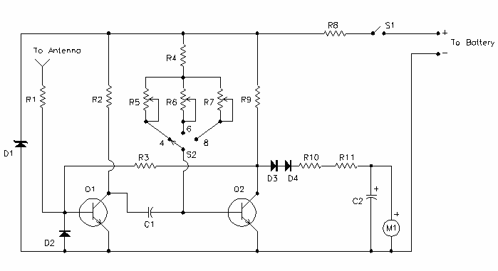
Wireless Auto Tachometer
Anyone performing their own automobile tune-ups knows how important it is to know your engine's speed. With this tachometer, you can measure your engine's speed without any connections or annoying timing lights.
The described tachometer is a non-invasive device designed for...
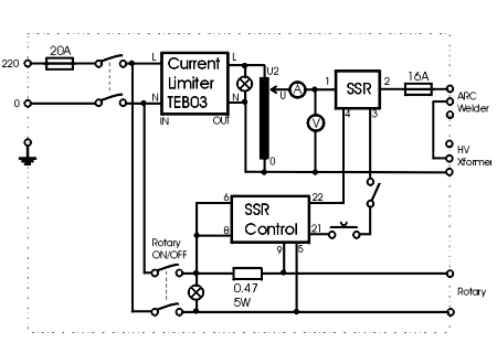
Power Control Unit
This shows the overall circuit diagram of the power control unit. On the left, there is a main relay controlled by the key switch.
The power control unit circuit diagram illustrates the primary components and their interconnections for managing electrical power...