


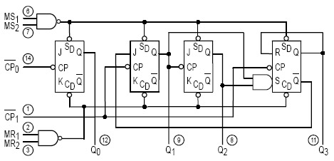
74LS Datasheets
#RF remote
#toggle mode
#momentary mode
#BC549 NPN transistors
#relay control
#low voltage devices
#appliance control
#5V relays
#12V relays
#motor control
Description: A four-button RF remote control is designed to independently turn ON and OFF four different devices. Each of the four outputs can be configured to operate independently in either toggle or momentary mode. The outputs are buffered using BC549 NPN transistors, enabling them to drive low-voltage devices directly or connect to 5V or 12V relays (or motors) for controlling appliances that operate on 110V or 220V mains voltage, or any voltage of choice. Multiple remote systems can function independently to control more than four appliances in the same area by modifying the address code on the 433MHz receiver and remote. Additionally, it is feasible to use several remotes to control the same appliance, such as a garage door.
The four-button RF remote control system operates on a frequency of 433 MHz, which is commonly used for remote control applications due to its effective range and reliability. The system consists of a transmitter (the remote) and a receiver unit that can be interfaced with various devices. Each button on the remote corresponds to a specific output channel on the receiver, allowing users to control multiple devices with a single handheld unit.
The configuration options for the outputs are significant for versatile applications. In toggle mode, pressing the button alternates the state of the output, turning the connected device ON if it is OFF, and vice versa. In momentary mode, the output remains active only while the button is pressed, which is useful for applications such as doorbells or temporary lighting.
The use of BC549 NPN transistors as buffers is a critical design choice. These transistors are capable of handling small loads directly, making them suitable for low-voltage devices. For higher power applications, the outputs can be connected to relays that can switch higher voltages, such as 110V or 220V, which are typical for household appliances. This flexibility allows the system to control a wide range of devices, from simple LED lights to larger motors or heating elements.
To expand the system's capabilities, users can modify the address codes of the receiver and remote. This feature allows multiple systems to coexist in the same environment without interference, enabling the control of more than four devices. Furthermore, the ability to use multiple remotes for a single appliance adds convenience, particularly in applications like garage doors, where multiple users may need access.
Overall, this RF remote control system provides a robust and flexible solution for wireless device management, integrating easily into various home automation setups while maintaining user-friendly operation.Four button RF remote is used to turn ON / OFF four different devices independently. Any of the four outputs can be configured to work independently in either toggle or momentary mode. Outputs are buffered by BC549 NPN transistors and can drive low voltage devices directly or be connected to either 5V or 12V relays (or motors) to control appliance s that use 110V / 220V mains voltage or any voltage of your choice. Multiple remote systems can be used independently to control more than four appliances in the same location by changing the address code on 433MHz receiver and remote. It is also possible to use several remotes to control the same appliance such as garage door.
The four-button RF remote control system operates on a frequency of 433 MHz, which is commonly used for remote control applications due to its effective range and reliability. The system consists of a transmitter (the remote) and a receiver unit that can be interfaced with various devices. Each button on the remote corresponds to a specific output channel on the receiver, allowing users to control multiple devices with a single handheld unit.
The configuration options for the outputs are significant for versatile applications. In toggle mode, pressing the button alternates the state of the output, turning the connected device ON if it is OFF, and vice versa. In momentary mode, the output remains active only while the button is pressed, which is useful for applications such as doorbells or temporary lighting.
The use of BC549 NPN transistors as buffers is a critical design choice. These transistors are capable of handling small loads directly, making them suitable for low-voltage devices. For higher power applications, the outputs can be connected to relays that can switch higher voltages, such as 110V or 220V, which are typical for household appliances. This flexibility allows the system to control a wide range of devices, from simple LED lights to larger motors or heating elements.
To expand the system's capabilities, users can modify the address codes of the receiver and remote. This feature allows multiple systems to coexist in the same environment without interference, enabling the control of more than four devices. Furthermore, the ability to use multiple remotes for a single appliance adds convenience, particularly in applications like garage doors, where multiple users may need access.
Overall, this RF remote control system provides a robust and flexible solution for wireless device management, integrating easily into various home automation setups while maintaining user-friendly operation.Four button RF remote is used to turn ON / OFF four different devices independently. Any of the four outputs can be configured to work independently in either toggle or momentary mode. Outputs are buffered by BC549 NPN transistors and can drive low voltage devices directly or be connected to either 5V or 12V relays (or motors) to control appliance s that use 110V / 220V mains voltage or any voltage of your choice. Multiple remote systems can be used independently to control more than four appliances in the same location by changing the address code on 433MHz receiver and remote. It is also possible to use several remotes to control the same appliance such as garage door.
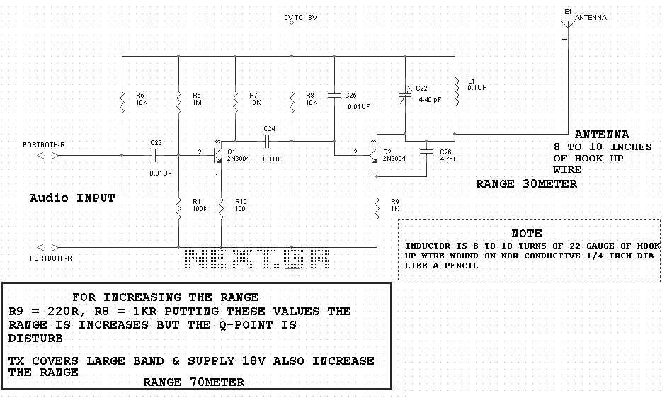
motor timer
The primary concept is to rotate the motor slightly every 15 seconds. A monofilament line conveys the motion to the ornament, which is wound by the motor and gradually unwinds as the ornament turns. The charging circuit includes a 1...
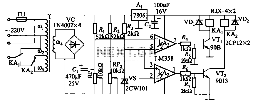
Relay control auto-transformer AC power supply circuit
It utilizes two LM358 operational amplifiers, A2 and Ar, to create a voltage measurement comparison control circuit for upper and lower limit voltage settings. The circuit includes a Raspberry Pi adjustment potentiometer (RPi) and an additional potentiometer (RP2) to modify...
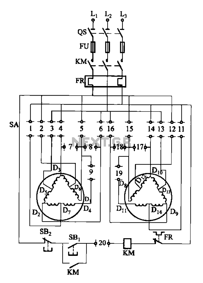
2Y-Y-2 - connection four-speed motor switch control circuit
The 3-119 circuit shown in the figure combines switch SA to realize the stator windings, specifically the 2, Y, and 2Y connections, which correspond to the motor speed n1.
The 3-119 circuit is designed to facilitate the control of motor speed...
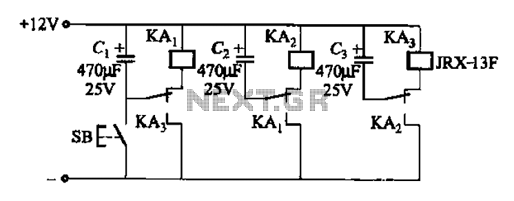
Alternately flashing one of a plurality of sets of high-power lights a chain circuit
The relay control allows for multiple pairs of contacts to be connected in parallel, enabling the circuit to handle a large lamp power. The design is straightforward; by simply changing the capacitance of the capacitor, different flash frequencies can be...
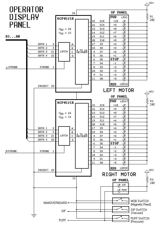
Dual-Motor SIP&PUFF Controlled Kayak System
The YouTube video below demonstrates the quick and easy setup of the system at the launch site.
The provided description indicates a focus on the efficiency of system installation at a launch site, as showcased in a YouTube video. In an...
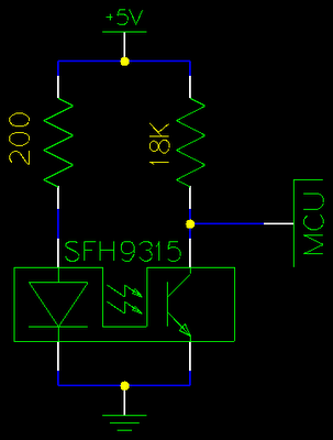
Gray Projects
After learning to operate the device, it became evident that inertia posed a significant challenge. The constructed system is notably heavy, making it difficult to initiate motor operation at full speed. Despite having some understanding of physics, practical experience is...
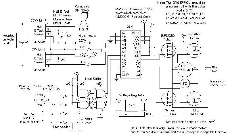
Motorized Video Camera Mount
The camera rotator circuit utilizes a 2716 EPROM to store a logic value table that governs the motor driver (H-bridge) circuit. The schematic illustrates the EPROM data. By employing the EPROM, a significant number of discrete gates are eliminated. The...
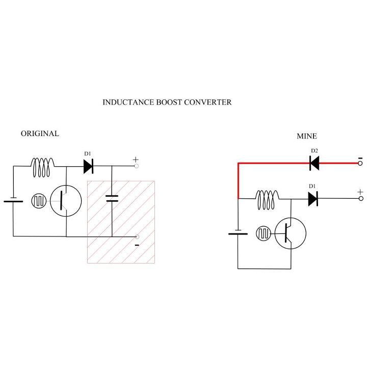
My Motors got me to Tap into Radiant Energy
A new user is seeking to share information about their experiences on this platform.
The user expresses a desire to communicate and engage with the community regarding their experiences. This indicates an interest in exchanging knowledge and possibly seeking assistance or...
2Y-Y-2 - connection four-speed motor switch control circuit
The 3-119 circuit shown in the figure combines switch SA to realize the stator windings, specifically the 2, Y, and 2Y connections, which correspond to the motor speed n1.
The 3-119 circuit is designed to facilitate the control of motor speed...