


IR to RF converter circuit
#IR
#RF
#transmitter
#remote control
#ASK transmitter
#signal conversion
#long range
#wireless
#St-TX 01
#line of sight
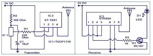
Description: The IR to RF transmitter circuit described here can convert infrared (IR) signals from a remote control into radio frequency (RF) signals, allowing for long-distance transmission. This circuit effectively extends the range of an IR remote control and does not require a direct line of sight due to the use of RF signals. The transmitter utilizes a ST-TX 01 ASK transmitter IC (IC2). The IR signals received by IC1 (TSOP 1738) are converted into RF signals by IC2 and transmitted via an antenna. The transmitter operates with a power output of 16 dBm at a 5V supply. The receiver employs a ST-RX04 ASK receiver IC (IC3), which receives the transmitted code, decodes it back to the original IR code, and retransmits it through an IR LED (D1). A transistor (Q1) is used to drive the IR LED (D1) based on the output from pin 2 of IC3.
The circuit comprises several key components that work together to facilitate the conversion and transmission of signals. The TSOP 1738, an IR receiver module, captures the IR signals emitted by a remote control. It outputs a digital signal that corresponds to the received IR code. This output is fed into the ST-TX 01 ASK transmitter IC (IC2), which modulates the digital signal onto a carrier frequency suitable for RF transmission. The modulation process allows the signal to be effectively transmitted over greater distances compared to standard IR communication.
The antenna connected to the ST-TX 01 transmitter plays a crucial role in radiating the RF signals into the surrounding environment. The design ensures that the transmitter operates efficiently at a power output of 16 dBm, which is adequate for typical remote control applications, allowing for a significant range of operation.
On the receiving end, the ST-RX04 ASK receiver IC (IC3) captures the RF signals transmitted by the ST-TX 01. IC3 demodulates the received RF signal, extracting the original digital signal that represents the IR code. This demodulated signal is then sent to the output pin (pin 2), which drives the base of the transistor (Q1). The transistor acts as a switch, controlling the current flow to the IR LED (D1), which emits the infrared light corresponding to the original remote control signal.
This configuration allows for seamless communication between the remote control and the receiving device, effectively overcoming the limitations of traditional IR communication, such as the need for line of sight. The overall design is suitable for various applications, including remote control systems for TVs, audio equipment, and other consumer electronics, enhancing user convenience and operational range.The IR to RF transmitter circuit given here can convert the IR signals from your remote to RF signals to long distances. The circuit given here is a good one for extending the range of your IR remote. Also such systems does not need a line of sight since RF signals are used. The transmitter is based on a St-TX 01 ASK transmitter IC (IC2). The IR sig nals falling on IC 1 (TSOP 1738) will be converted to RF signals by IC2 and transmitted through antenna. The transmitter has a power output of 16dBm at 5V supply. The receiver is based on a ST-RX04 ASK receiver IC (IC3). The IC3 receives the transmitted code, decodes it to the original IR code and re transmits through IR LED (D1).
The transistor Q1 is used to drive the D1 from the output of the IC3(pin2).
The circuit comprises several key components that work together to facilitate the conversion and transmission of signals. The TSOP 1738, an IR receiver module, captures the IR signals emitted by a remote control. It outputs a digital signal that corresponds to the received IR code. This output is fed into the ST-TX 01 ASK transmitter IC (IC2), which modulates the digital signal onto a carrier frequency suitable for RF transmission. The modulation process allows the signal to be effectively transmitted over greater distances compared to standard IR communication.
The antenna connected to the ST-TX 01 transmitter plays a crucial role in radiating the RF signals into the surrounding environment. The design ensures that the transmitter operates efficiently at a power output of 16 dBm, which is adequate for typical remote control applications, allowing for a significant range of operation.
On the receiving end, the ST-RX04 ASK receiver IC (IC3) captures the RF signals transmitted by the ST-TX 01. IC3 demodulates the received RF signal, extracting the original digital signal that represents the IR code. This demodulated signal is then sent to the output pin (pin 2), which drives the base of the transistor (Q1). The transistor acts as a switch, controlling the current flow to the IR LED (D1), which emits the infrared light corresponding to the original remote control signal.
This configuration allows for seamless communication between the remote control and the receiving device, effectively overcoming the limitations of traditional IR communication, such as the need for line of sight. The overall design is suitable for various applications, including remote control systems for TVs, audio equipment, and other consumer electronics, enhancing user convenience and operational range.The IR to RF transmitter circuit given here can convert the IR signals from your remote to RF signals to long distances. The circuit given here is a good one for extending the range of your IR remote. Also such systems does not need a line of sight since RF signals are used. The transmitter is based on a St-TX 01 ASK transmitter IC (IC2). The IR sig nals falling on IC 1 (TSOP 1738) will be converted to RF signals by IC2 and transmitted through antenna. The transmitter has a power output of 16dBm at 5V supply. The receiver is based on a ST-RX04 ASK receiver IC (IC3). The IC3 receives the transmitted code, decodes it to the original IR code and re transmits through IR LED (D1).
The transistor Q1 is used to drive the D1 from the output of the IC3(pin2).
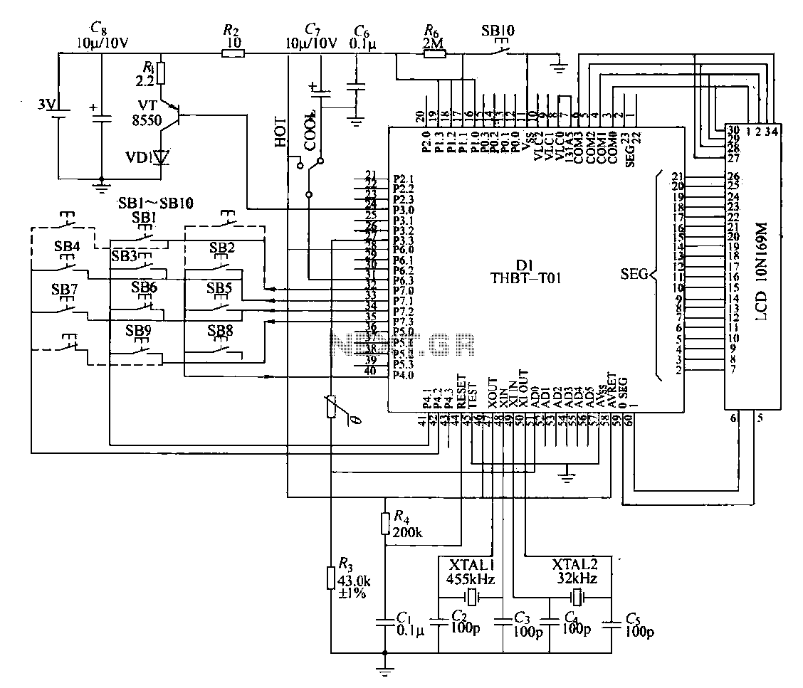
Remote control transmitter circuit
The circuit composition of a specific remote control transmitter is illustrated in a diagram. The transmitter primarily consists of a large-scale integrated circuit chip (D1, THBT-T01), a 4.5 kHz crystal oscillator, a 32 kHz crystal oscillator, a liquid crystal display...
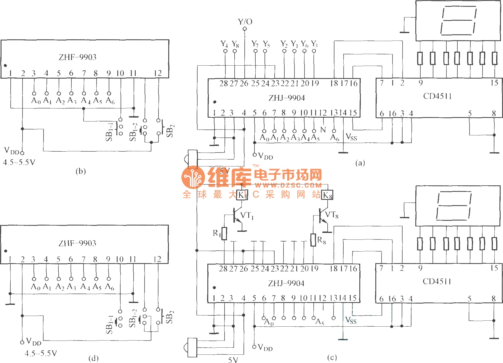
The eight-way remote control circuit diagram composed of module
This is an eight-way signal remote control selection circuit composed of ZHJ-9904. It includes a remote control transmitter circuit, an eight-way switch control circuit, and a remote control transmitter.
The eight-way signal remote control selection circuit utilizing the ZHJ-9904 is designed...
Projects
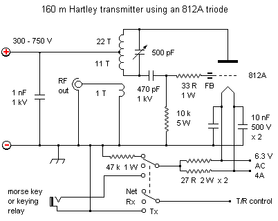
This project was inspired by a desire to create something unique rather than with the expectation of it becoming a practical transmitter. At the time of writing, the project is in the breadboarding phase, and a decision has yet to...
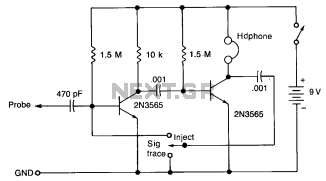
Single injector-tracer
In the "Trace" mode, the non-linear operation of the amplifier will detect modulated RF signals, which will be filtered by the 0.001 µF capacitor and heard in the headphones. In the "Inject" mode, this circuit will provide a nominal square...
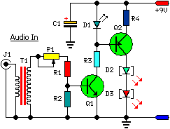
A Low Power Wireless Audio Power Amplifier circuit
This low-cost project enables audio reproduction from a television without disturbing others. It eliminates the need for wired connections between the TV and loudspeakers. Instead, it utilizes invisible infrared light to transmit audio signals from the TV to the loudspeakers....
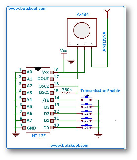
building rf remote control
The simplest approach to creating a remote-controlled robot is to repurpose a low-cost wireless toy car by removing its receiver module and remote control. Alternatively, one can design a custom RF remote using an ASK (Amplitude Shift Keying) based transmitter/receiver...
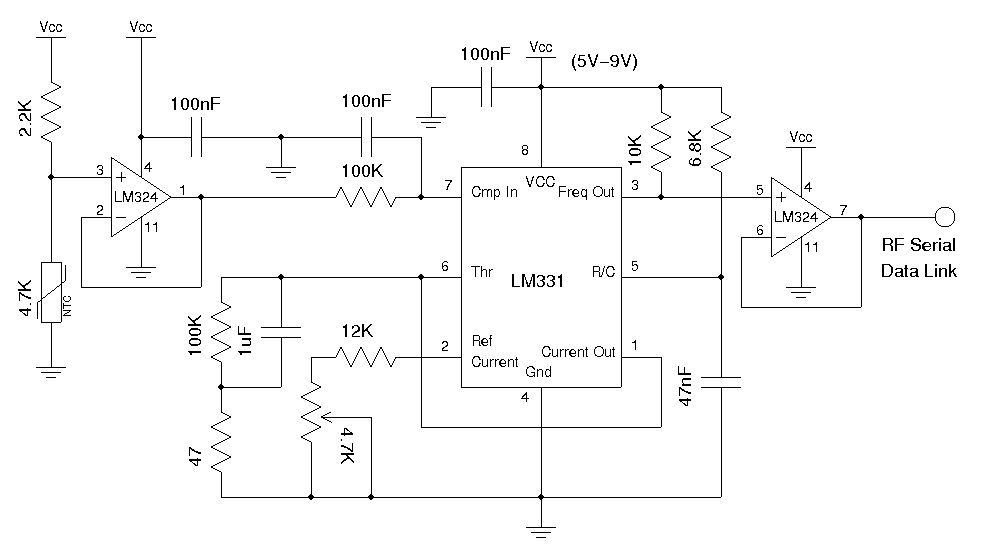
Building a Wireless Temperature Sensor
A wireless temperature sensor allows temperature measurements to be taken anywhere within the range of the transmitter and receiver. One straightforward approach to achieve this is by utilizing a voltage-to-frequency conversion chip in conjunction with an analog temperature sensor, such...
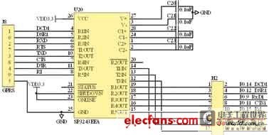
the design of the intellectual wireless signal transducer of ARM
The intellectual wireless signal transducer is designed for major transducer applications and typical sensor output signal designs. It is essential to first analyze the outgoing signals from the transducer. Typically, the output of the transducer is a standard electric current...
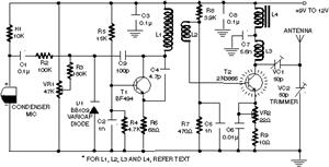
transmitter circuit diagram
Clearly indicate on the circuit diagram each type and size of the components. There is a need for assistance in designing a low power FM transmitter circuit, specifically using the BA1404 FM transmitter with a center frequency of 79W and...