


LED (IR LED1) and the phototransistor (T1) and wireless light switch
#IR LED
#phototransistor
#wireless
#light switch
#infrared
#sensor
#remote control
#hand dryer
#flush system
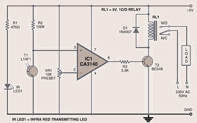
Description: The wireless light switch circuit described here requires no physical contact for operating the appliance. You just need to move your hand between the infrared LED (IR LED1) and the phototransistor (T1). The infrared rays transmitted by IR LED1 are detected by the phototransistor to activate the hidden lock, flush system, hand dryer, or other devices. This wireless light switch is very stable and sensitive compared to other AC appliance control circuits. It is simple, compact, and inexpensive. Current consumption is low in milliamperes. The circuit is built around an IC CA3140, IR LED1, phototransistor, and other discrete components. The operation of the circuit is straightforward. To switch on the appliance, it is necessary to interrupt the infrared rays falling on the phototransistor with a hand. During this interruption, the appliance remains on through the relay. When the hand is removed from the infrared beam, the appliance turns off via the relay.
The wireless light switch circuit utilizes an infrared light-emitting diode (IR LED1) and a phototransistor (T1) to create a non-contact switch mechanism. The core of the circuit is based around the CA3140 operational amplifier, which provides the necessary gain and stability for the phototransistor's output signal. When a user moves their hand into the path of the infrared beam emitted from IR LED1, the phototransistor detects the change in light intensity, leading to a change in its conductive state.
This circuit operates at low power, making it energy-efficient for various applications, including lighting systems, automated doors, and other household appliances. The relay component acts as a switch that controls the power to the appliance. When the infrared beam is interrupted, the phototransistor triggers the relay, allowing current to flow to the connected device. The relay remains activated as long as the beam is interrupted. Once the hand is removed, the infrared light reaches the phototransistor again, causing it to turn off and subsequently deactivating the relay, which in turn powers down the appliance.
The design is compact and cost-effective, making it suitable for various applications where traditional mechanical switches may be impractical. The use of infrared technology enhances the reliability and longevity of the switch, as there are no moving parts that can wear out over time. Additionally, the low current consumption in milliamperes ensures that the circuit can operate efficiently without excessive energy use, contributing to its appeal in modern electronic applications.The wireless light switch circuit described here requires no physical contact for operating the appliance. You just need to move your hand between the infrared LED (IR LED1) and the phototransistor (T1). The infrared rays transmitted by IR LED1 is detected by the phototransistor to activate the hidden lock, flush system, hand dryer or else.
This w ireless light switch is very stable and sensitive compared to other AC appliance control circuits. It is simple, compact and cheap. Current consumption is low in milliamperes. The circuit is built around an IC CA3140, IRLED1, phototransistor and other discrete components. The working of the circuit is simple. In order to switch on the appliance, you simply interrupt the infrared rays falling on the phototransistor through your hand. During the interruption, the appliance remains on through the relay. When you remove your hand from the infrared beam, the appliance turns off through the relay.
The wireless light switch circuit utilizes an infrared light-emitting diode (IR LED1) and a phototransistor (T1) to create a non-contact switch mechanism. The core of the circuit is based around the CA3140 operational amplifier, which provides the necessary gain and stability for the phototransistor's output signal. When a user moves their hand into the path of the infrared beam emitted from IR LED1, the phototransistor detects the change in light intensity, leading to a change in its conductive state.
This circuit operates at low power, making it energy-efficient for various applications, including lighting systems, automated doors, and other household appliances. The relay component acts as a switch that controls the power to the appliance. When the infrared beam is interrupted, the phototransistor triggers the relay, allowing current to flow to the connected device. The relay remains activated as long as the beam is interrupted. Once the hand is removed, the infrared light reaches the phototransistor again, causing it to turn off and subsequently deactivating the relay, which in turn powers down the appliance.
The design is compact and cost-effective, making it suitable for various applications where traditional mechanical switches may be impractical. The use of infrared technology enhances the reliability and longevity of the switch, as there are no moving parts that can wear out over time. Additionally, the low current consumption in milliamperes ensures that the circuit can operate efficiently without excessive energy use, contributing to its appeal in modern electronic applications.The wireless light switch circuit described here requires no physical contact for operating the appliance. You just need to move your hand between the infrared LED (IR LED1) and the phototransistor (T1). The infrared rays transmitted by IR LED1 is detected by the phototransistor to activate the hidden lock, flush system, hand dryer or else.
This w ireless light switch is very stable and sensitive compared to other AC appliance control circuits. It is simple, compact and cheap. Current consumption is low in milliamperes. The circuit is built around an IC CA3140, IRLED1, phototransistor and other discrete components. The working of the circuit is simple. In order to switch on the appliance, you simply interrupt the infrared rays falling on the phototransistor through your hand. During the interruption, the appliance remains on through the relay. When you remove your hand from the infrared beam, the appliance turns off through the relay.

InfraRed Remote Switch
This Project REMOTE CONTROLLED SWITCH BOARD is used to switch on/off the Home Appliances by using a standard Remote control. The system is used to switch on/off up to six electrical devices. All the above processes are controlled by the...
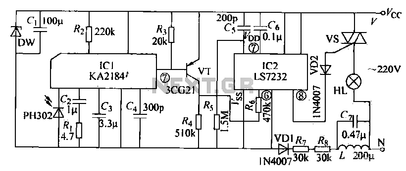
Infrared control dimming circuit
The receiving circuit operates as follows: when the infrared receiver detects a signal from the remote control transmitter, the KA2184 processes this signal, resulting in a low output at the pin. This low output is directly connected to the base...
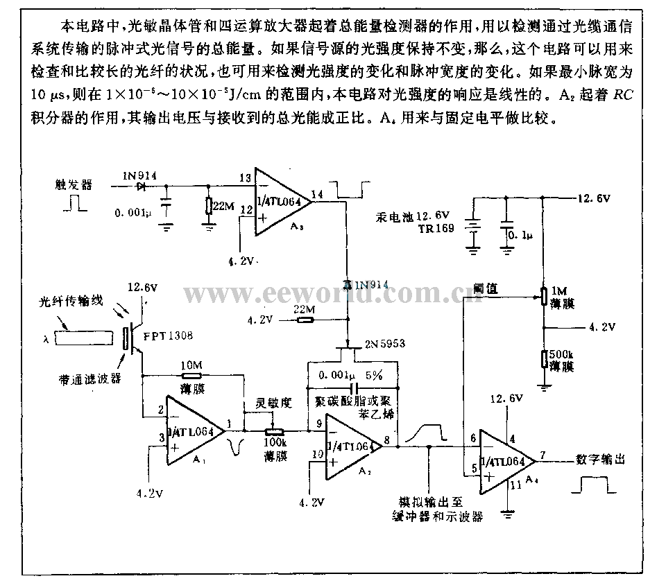
Optical transmission detection circuit
This circuit employs a phototransistor along with four operational amplifiers to function as a total energy detector. It is designed to measure the total energy of optical pulses transmitted through an optical cable communication system. When the light intensity of...
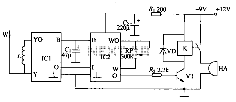
Infrared burglar alarm circuit
An infrared reflective burglar alarm utilizes infrared detection through reflective components, with a maximum detection range of up to 12 meters to trigger an alarm. When an intrusion is detected, a realistic barking sound is emitted to alert the owner...
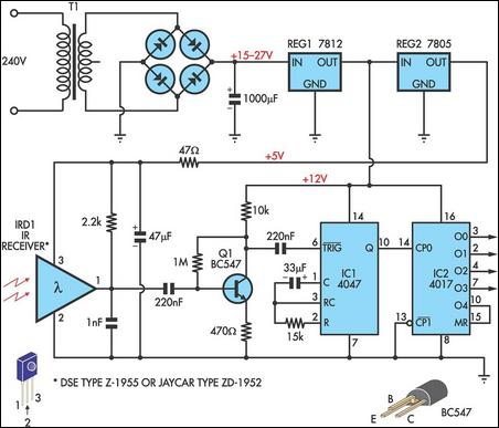
Infrared Remote Receiver Has Four Outputs
This circuit allows any infrared (IR) remote control to manage the outputs of a 4017 decade counter. It utilizes a 3-terminal IR receiver (IRD1) to capture infrared signals from the transmitter. The output from IRD1 is connected to an NPN...

infrared toggle switch for home
The infrared (IR) toggle switch project described here aims to provide a control mechanism for electrical appliances that lack remote operation features. The goal is to construct a black box where users can plug in their 120V AC appliance and...
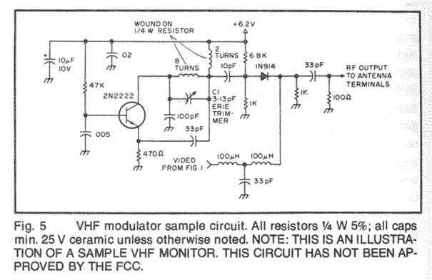
Video/Audio Wireless Transmitter
In this fast-paced world, there is little time for inconveniences and a greater need for portability and adaptability. The idea for an Audio/Video transmitter stems from this need. There may have been times when you’ve wanted to hook up your...
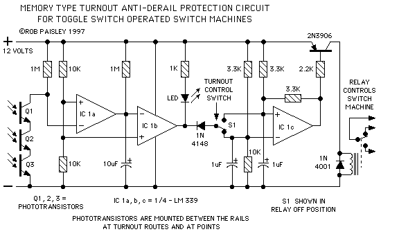
Protector
The circuits presented here will prevent turnouts from being thrown while a train is on a switch, which is ideal in situations where the switch cannot be seen by the operator. They utilize phototransistor sensors to detect the presence of...
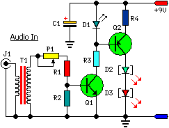
A Low Power Wireless Audio Power Amplifier circuit
This low-cost project enables audio reproduction from a television without disturbing others. It eliminates the need for wired connections between the TV and loudspeakers. Instead, it utilizes invisible infrared light to transmit audio signals from the TV to the loudspeakers....