


Magneto circuit diagram of a remote control switch
#magnetic switch
#remote control
#automatic
#reliable
#low failure
#versatile
#output performance
#conversion
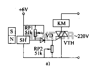
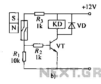
Description: The automatic weapon features a magnetic switch circuit that is simple, reliable, has a low failure rate, and offers good versatility. It can be used for output performance or converted into mechanical displacement applications. The circuit diagram utilizes a Hall switch (SH) magnetic device. When the magnet moves away from the Hall switch circuit, the fixed bias magnet causes the Hall switch circuit to turn on, resulting in a low output that turns off the thyristor and releases the AC contactor (KM). Conversely, when the magnet enters the sensitive area of the Hall switch, the output suddenly increases to a high level, causing diode VD to conduct and activating KM. Adjustments to RP1 and RP2 can be made to balance sensitivity and reliability, preventing false triggering of VT. Figure 18-29b illustrates a magnetron device using a reed switch (KP). When the magnet is removed from the KR, the KR contacts open, turning off the transistor and releasing relay KD. When the magnet approaches KP, the KP contacts close, activating KD, which controls the electrical equipment in the system. The movement and position of the magnet determine the operational status of the device. If the relay coil current is low or the electrical equipment operates at low voltage, it can be connected in series with the reed switch, minimizing the need for additional components. Since reed contacts typically have low capacity, larger loads require the use of transistors, relays, or contactors to amplify voltage and current. The thyristor gate requires low voltage and current, thus necessitating the connection of the reed switch to the thyristor control circuit, with the electrical equipment connected to the thyristor's main circuit, which is an effective solution.
The magnetic switch circuit described serves as a versatile control mechanism for various applications, specifically in automatic weapon systems. The Hall effect sensor is a critical component, providing a non-contact means to detect the presence of a magnetic field. This feature enhances the reliability of the circuit, as it minimizes mechanical wear and tear associated with traditional switch mechanisms.
In the operational sequence, when the magnet is removed from the proximity of the Hall switch, the circuit enters a low-output state, which effectively disables connected devices. This is achieved through the thyristor, which acts as a controlled switch that can handle significant loads while being triggered by a minimal input current. The design allows for the integration of adjustable resistors (RP1 and RP2) to fine-tune the sensitivity of the Hall switch, ensuring that the system can adapt to varying environmental conditions without false triggering.
The use of a reed switch in conjunction with the Hall switch enhances the circuit's functionality. The reed switch serves as a secondary control mechanism, allowing for the direct operation of low-power devices. In cases where the load demands exceed the reed switch's capacity, the circuit can leverage transistors or relays to manage higher power levels safely. This is particularly relevant in applications where operational reliability is paramount.
The thyristor's role in the circuit is crucial, as it provides a robust method for managing the power delivered to the load. By connecting the thyristor's gate to the reed switch, the circuit maintains a low-power control signal while enabling the handling of high-power loads. This configuration not only simplifies the overall design but also enhances the safety and efficiency of the system.
In summary, the described magnetic switch circuit offers a reliable, efficient, and adaptable solution for automatic weapon systems, utilizing both Hall effect sensors and reed switches to achieve precise control over electrical equipment. The careful integration of components ensures that the system operates effectively under varying conditions while maintaining high reliability and low failure rates.Features automatic weapons such magnetic switch circuit is very simple, reliable, low failure rate, good versatility, can be used to output the performance or can be converted into mechanical displacement of the occasion. (2) is a circuit diagram using the Hall switch (SH) magnetron devices. When the magnet away from the Hall switch circuit, due to the positive effect of the fixed bias magnet, the Hall switch circuit is turned on, the output is low, the thyristor is turned off, AC contactor KM release. While the magnet is moving into sensitive areas Hall switch when in the reverse magnetic field whose output suddenly promoted to the high level, by making the diode VD VT conduction, KM pull.
Adjust RP1 and RP2, can take into account the sensitivity and reliable offerings (to prevent false triggering VT). Figure 18-29b is in magnetron device using reed (KP) is. When the magnet away from the KR, KR contacts open, transistor is turned off, the relay is KD released.
In the magnet close to the KP, KP contact closure, KD suction units, relay contacts KD string controlled electrical equipment control system circuit, so the movement of the magnet and its location determines the working status of the device.. (3) analysis of the circuit shown in circles 18-29, KD if the relay coil current is small, or low voltage electrical equipment, current is very small, it can be directly connected in series with the reed pipe, with less than other components.
Reed contacts generally small capacity, control large capacity of the load resistance, we must use transistors, relay embroidery, or the like contactor thyristor as voltage, current, or persuade amplifying. Since the thyristor gate voltage is low, current is very small, therefore, the reed switch connected to the thyristor control pole circuit required, electrical equipment connected to the thyristor main road in the pigsty, which is a better solution.
The magnetic switch circuit described serves as a versatile control mechanism for various applications, specifically in automatic weapon systems. The Hall effect sensor is a critical component, providing a non-contact means to detect the presence of a magnetic field. This feature enhances the reliability of the circuit, as it minimizes mechanical wear and tear associated with traditional switch mechanisms.
In the operational sequence, when the magnet is removed from the proximity of the Hall switch, the circuit enters a low-output state, which effectively disables connected devices. This is achieved through the thyristor, which acts as a controlled switch that can handle significant loads while being triggered by a minimal input current. The design allows for the integration of adjustable resistors (RP1 and RP2) to fine-tune the sensitivity of the Hall switch, ensuring that the system can adapt to varying environmental conditions without false triggering.
The use of a reed switch in conjunction with the Hall switch enhances the circuit's functionality. The reed switch serves as a secondary control mechanism, allowing for the direct operation of low-power devices. In cases where the load demands exceed the reed switch's capacity, the circuit can leverage transistors or relays to manage higher power levels safely. This is particularly relevant in applications where operational reliability is paramount.
The thyristor's role in the circuit is crucial, as it provides a robust method for managing the power delivered to the load. By connecting the thyristor's gate to the reed switch, the circuit maintains a low-power control signal while enabling the handling of high-power loads. This configuration not only simplifies the overall design but also enhances the safety and efficiency of the system.
In summary, the described magnetic switch circuit offers a reliable, efficient, and adaptable solution for automatic weapon systems, utilizing both Hall effect sensors and reed switches to achieve precise control over electrical equipment. The careful integration of components ensures that the system operates effectively under varying conditions while maintaining high reliability and low failure rates.Features automatic weapons such magnetic switch circuit is very simple, reliable, low failure rate, good versatility, can be used to output the performance or can be converted into mechanical displacement of the occasion. (2) is a circuit diagram using the Hall switch (SH) magnetron devices. When the magnet away from the Hall switch circuit, due to the positive effect of the fixed bias magnet, the Hall switch circuit is turned on, the output is low, the thyristor is turned off, AC contactor KM release. While the magnet is moving into sensitive areas Hall switch when in the reverse magnetic field whose output suddenly promoted to the high level, by making the diode VD VT conduction, KM pull.
Adjust RP1 and RP2, can take into account the sensitivity and reliable offerings (to prevent false triggering VT). Figure 18-29b is in magnetron device using reed (KP) is. When the magnet away from the KR, KR contacts open, transistor is turned off, the relay is KD released.
In the magnet close to the KP, KP contact closure, KD suction units, relay contacts KD string controlled electrical equipment control system circuit, so the movement of the magnet and its location determines the working status of the device.. (3) analysis of the circuit shown in circles 18-29, KD if the relay coil current is small, or low voltage electrical equipment, current is very small, it can be directly connected in series with the reed pipe, with less than other components.
Reed contacts generally small capacity, control large capacity of the load resistance, we must use transistors, relay embroidery, or the like contactor thyristor as voltage, current, or persuade amplifying. Since the thyristor gate voltage is low, current is very small, therefore, the reed switch connected to the thyristor control pole circuit required, electrical equipment connected to the thyristor main road in the pigsty, which is a better solution.
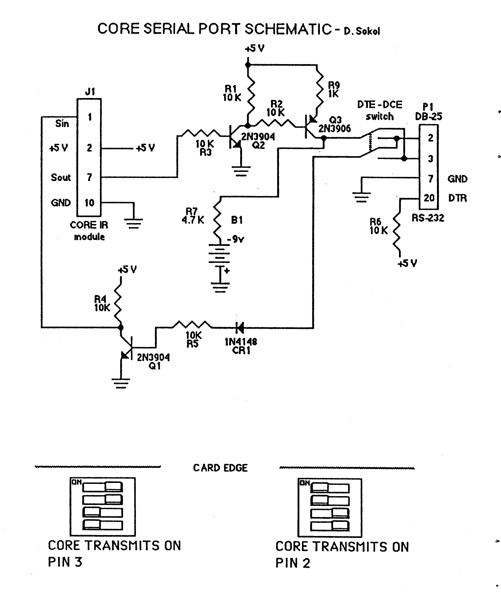
Core Remote Control Unit
If the unit has been idle for an extended period due to depleted AAA batteries, resulting in a malfunctioning display or inoperability, the most likely requirement is the replacement of the internal lithium battery. Although the unit was advanced for...
Remote Control Toy Car Schematic
The following circuit illustrates a schematic diagram for a remote control toy car. Features: it does not affect the performance of the original design.
The remote control toy car schematic circuit diagram typically consists of several key components that work together...
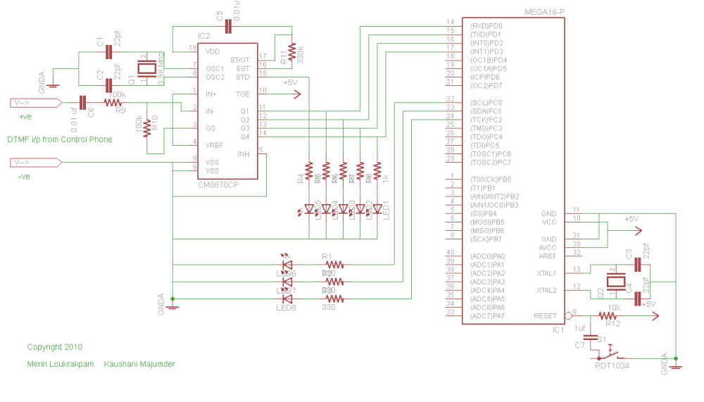
Home Automation through Cellphone Keying
This project was developed during a Bachelor of Engineering course to enable remote control of lights and other appliances within a room. The objective was to address the common issue of forgetting to turn off devices such as fans or...
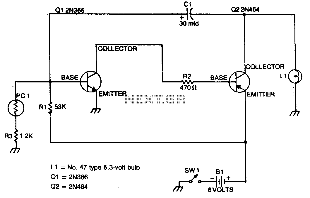
Automatic safety flasher
This flasher activates only during nighttime, providing bright illumination and automatically turning off when sunlight is detected. The photocell should be positioned on top of the unit to maximize light detection.
The circuit for the nighttime flasher utilizes a photocell sensor...
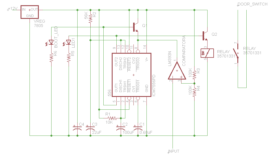
door opener science project
This button, with some modifications, allows the opening of an office door using Nexus One, iPhone, or SMS. Positioned near the reception desk, this button activates an electronic latch on the front door. Upon removing the assembly from the wall,...
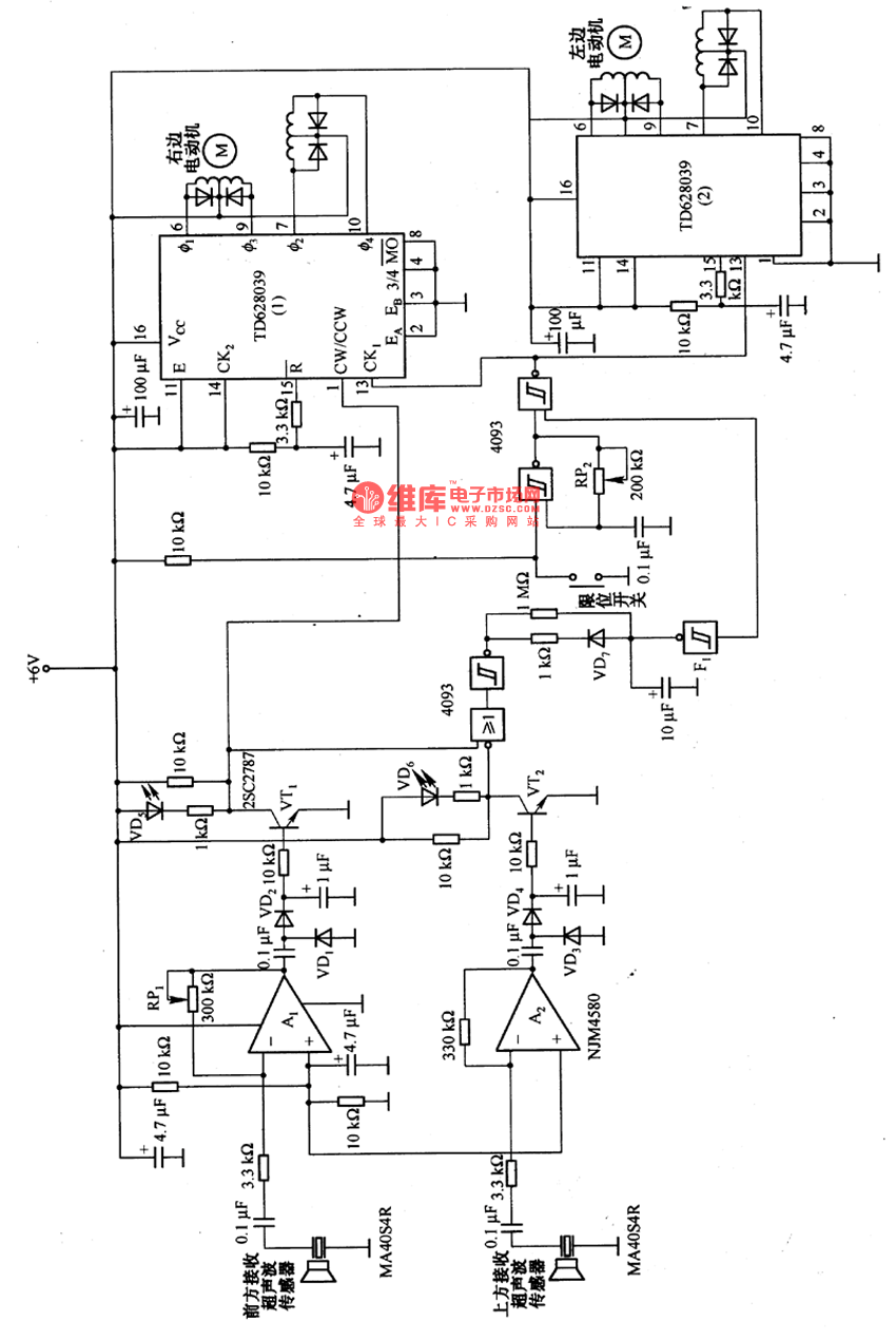
Remote control robot circuit
The remote control robot circuit is illustrated in the accompanying figure. Figure 2-36(a) presents the circuit diagram, while figure 2-36(b) depicts the operating timing diagram. The robot's rotation process involves an ultrasonic launching circuit, which consists of a 40 kHz...
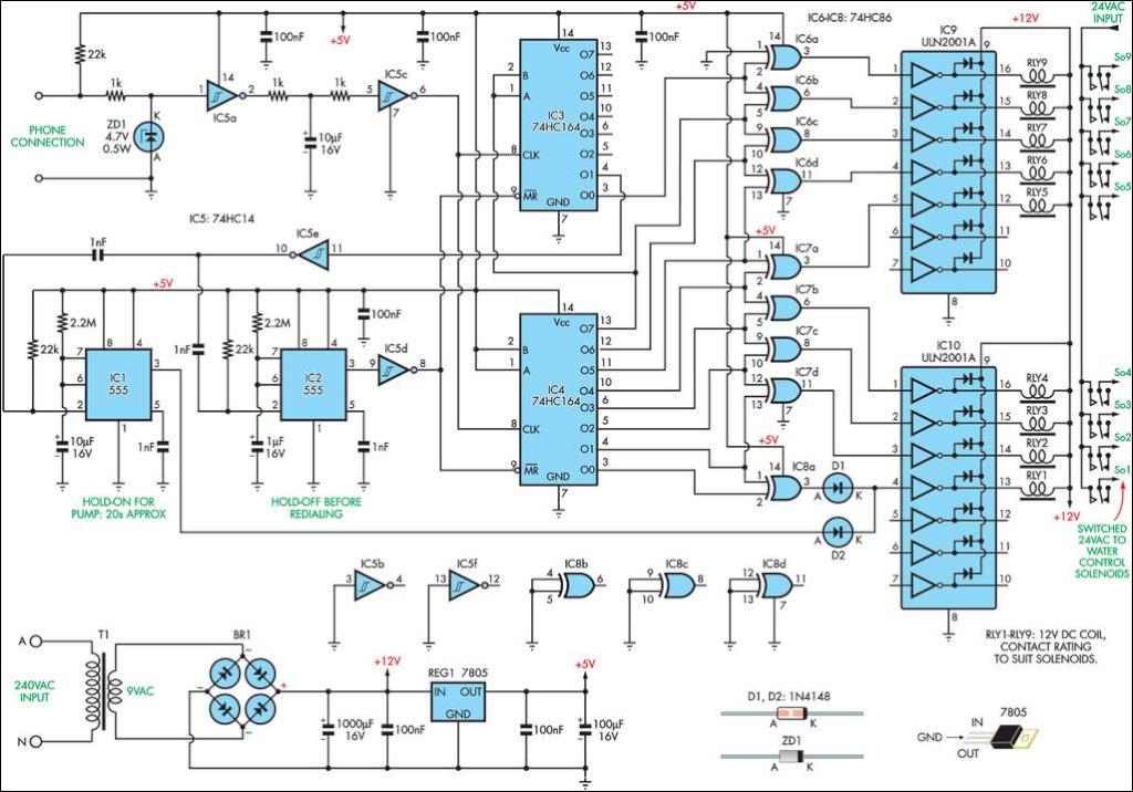
Inexpensive Remote Watering System
This remotely controlled watering system is both inexpensive and easy to expand. It is designed to operate in conjunction with a conventional watering timer.
The remotely controlled watering system is an innovative solution for automated irrigation, allowing users to manage watering...
Packard Bell Remote Control
When a key is pressed, the remote control transmits a preamble followed by 32 bits of information encoded using specific pulse timings. The pulse examples can be observed in logic analyzer screen captures, although some glitches are present due to...
Magneto Remote control switch circuit diagram
The automatic weapon features a magnetic switch circuit that is simple, reliable, has a low failure rate, and offers good versatility. It can be used to output performance or convert mechanical displacement. The circuit diagram utilizes a Hall switch (SH)...