


With a CD4013 produce laser light remote control switch
#CD4013
#laser
#remote control
#switch
#transformer
#bridge rectifier
#voltage regulator
#12V
#AC
#DC
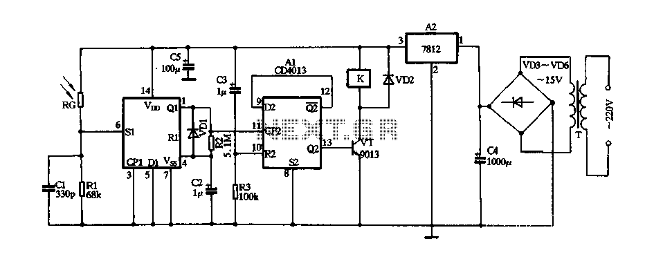
Description: The circuit consists of a 220V AC input connected to a step-down transformer (T), followed by a bridge rectifier (VD3 to VD6) and a three-terminal voltage regulator (block A2) that provides a stable 12V DC output for digital integrated circuits. The circuit includes a pair of D flip-flops (A1), where one D flip-flop is configured as a one-shot circuit with a transient time of approximately 0.7R2 x C2, resulting in a pulse width of 3.5 seconds. The other D flip-flop is configured as a bistable circuit to control a triac (VT) that drives a relay (K). Upon power-up, a differential circuit composed of capacitor C3 and resistor R3 generates a high-level pulse applied to the reset terminal (pin 10) of the flip-flop, causing the output Q2 to go low. This results in the transistor VT being turned off, preventing the relay K from activating and keeping the lamp off. The circuit is designed to be minimally affected by light, as a photosensitive resistor (RG) exhibits high resistance under laser irradiation. When the laser beam is directed at RG, it quickly lowers its resistance, triggering a high-level pulse at pin 6 of the D flip-flop (A1). This pulse activates the one-shot circuit, generating a high-level output pulse of 3.5 seconds from Q1. The integrated block connected to pin 11 (CP2) then flips, resulting in a high output at Q2 (pin 13), which turns on the triac VT and energizes the relay K, closing the normally open contact to power the lamp. Once the laser beam is removed from RG, the D flip-flop A1 resets, causing the output at Q2 to go low, turning off VT and de-energizing relay K, which subsequently turns off the lamp.
The circuit operates primarily on a 220V AC input, which is transformed down to a lower voltage suitable for the digital components. The step-down transformer serves to isolate the low-voltage section from high-voltage mains, enhancing safety. The rectification stage, utilizing a bridge rectifier configuration (VD3 to VD6), converts the AC voltage to pulsating DC, which is then smoothed and regulated by the three-terminal voltage regulator in block A2. This regulated output is crucial for the stable operation of the digital integrated circuits, ensuring they receive a consistent voltage level.
The D flip-flop configuration plays a significant role in the control logic of the circuit. The one-shot flip-flop provides a defined pulse width that can be adjusted by varying R2 and C2, allowing customization of the timing for the relay activation. The bistable flip-flop configuration allows for toggling the state of the relay based on the input conditions, making the circuit responsive to external stimuli, such as the laser beam.
The use of a photosensitive resistor (RG) adds an element of light sensitivity to the circuit. Its high resistance in the absence of light ensures that the relay remains off until the laser is activated. This design choice allows for precise control over the relay operation, making the circuit suitable for applications where light-based triggering is desired. Overall, the circuit demonstrates an effective integration of analog and digital components to achieve a reliable control mechanism for lighting based on laser input.FIG 220V AC by the step-down transformer T, VD3 ~ VD6 bridge rectifier and a three-terminal voltage regulator blocks A2, stable 12V DC voltage output for digital integrated cir cuits Al electricity. A1 is one pair of D flip-flop, wherein a D flip-flop connected into a one-shot circuit, the circuit transient time * 0.7R2 X C2 F3.5s; the other D flip-flops connected as bistable circuit for triac VT to drive the relay K action. Just when the power is turned on since the differential circuit C3, R3 composition generates a high level pulse is applied to its reset terminal pin 10, so that the output end Q2 of the output low level, the transistor VT cut-off, the relay K is not action, it controls the lamp does not light.
Usually less affected by photosensitive resistor RG laser irradiation showed high resistance, SI terminal that is 6 foot is asserted low. If using laser irradiation by light torch aligned RG ~, RG by Ying I immediately after the laser beam irradiation exhibit low resistance, in the first 6 feet namely Al Sl end produce students a high level pulse, one-shot circuit is triggered from Ql end outputs a high-level pulse width of 3.5s, added integrated block that is 11 feet CP2 end it turned over, Q2 ended output that is 13 feet high, VT conduction, K is energized by its control system is turned on normally open contact closure lights (not shown) power, lighting lights light.
And then the laser torch aligned RG irradiation time, Al and flipped once, that is 13 feet Q2 ended output low. VT ends, K loss of power release, lights off.
The circuit operates primarily on a 220V AC input, which is transformed down to a lower voltage suitable for the digital components. The step-down transformer serves to isolate the low-voltage section from high-voltage mains, enhancing safety. The rectification stage, utilizing a bridge rectifier configuration (VD3 to VD6), converts the AC voltage to pulsating DC, which is then smoothed and regulated by the three-terminal voltage regulator in block A2. This regulated output is crucial for the stable operation of the digital integrated circuits, ensuring they receive a consistent voltage level.
The D flip-flop configuration plays a significant role in the control logic of the circuit. The one-shot flip-flop provides a defined pulse width that can be adjusted by varying R2 and C2, allowing customization of the timing for the relay activation. The bistable flip-flop configuration allows for toggling the state of the relay based on the input conditions, making the circuit responsive to external stimuli, such as the laser beam.
The use of a photosensitive resistor (RG) adds an element of light sensitivity to the circuit. Its high resistance in the absence of light ensures that the relay remains off until the laser is activated. This design choice allows for precise control over the relay operation, making the circuit suitable for applications where light-based triggering is desired. Overall, the circuit demonstrates an effective integration of analog and digital components to achieve a reliable control mechanism for lighting based on laser input.FIG 220V AC by the step-down transformer T, VD3 ~ VD6 bridge rectifier and a three-terminal voltage regulator blocks A2, stable 12V DC voltage output for digital integrated cir cuits Al electricity. A1 is one pair of D flip-flop, wherein a D flip-flop connected into a one-shot circuit, the circuit transient time * 0.7R2 X C2 F3.5s; the other D flip-flops connected as bistable circuit for triac VT to drive the relay K action. Just when the power is turned on since the differential circuit C3, R3 composition generates a high level pulse is applied to its reset terminal pin 10, so that the output end Q2 of the output low level, the transistor VT cut-off, the relay K is not action, it controls the lamp does not light.
Usually less affected by photosensitive resistor RG laser irradiation showed high resistance, SI terminal that is 6 foot is asserted low. If using laser irradiation by light torch aligned RG ~, RG by Ying I immediately after the laser beam irradiation exhibit low resistance, in the first 6 feet namely Al Sl end produce students a high level pulse, one-shot circuit is triggered from Ql end outputs a high-level pulse width of 3.5s, added integrated block that is 11 feet CP2 end it turned over, Q2 ended output that is 13 feet high, VT conduction, K is energized by its control system is turned on normally open contact closure lights (not shown) power, lighting lights light.
And then the laser torch aligned RG irradiation time, Al and flipped once, that is 13 feet Q2 ended output low. VT ends, K loss of power release, lights off.
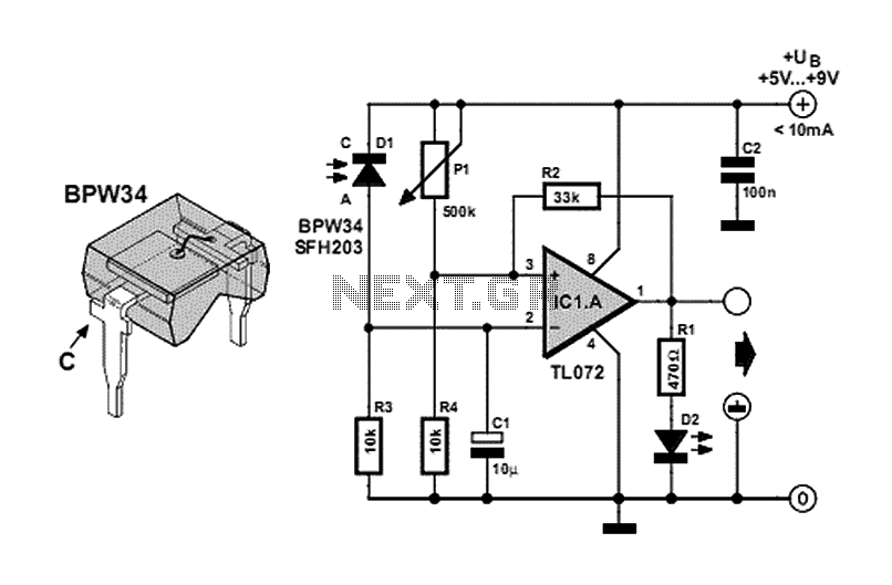
Laser Alarm
This circuit is a laser alarm system similar to those depicted in various movies. It employs a laser pointer beam to secure valuables and property. When the beam is interrupted by a person, animal, or object, the resistance of a...

PC 12V Adapter
This circuit provides short-circuit protection for a power supply derived from a PC's 12V output. It is particularly useful for projects involving PC interfacing. The circuit diagram illustrates the complete power supply setup. The necessary 12V voltage is sourced directly...
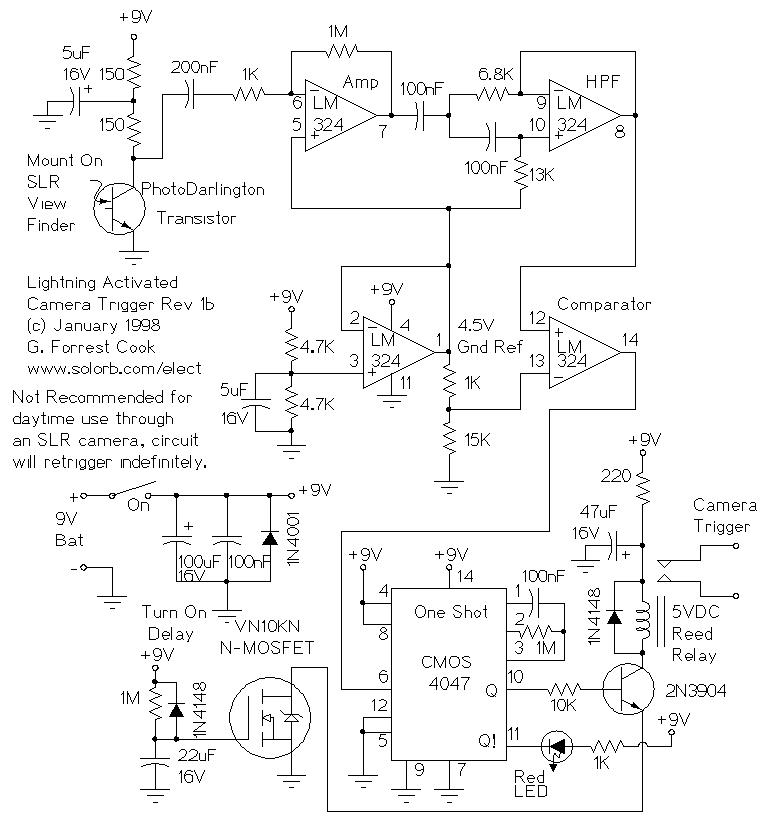
Optoelectronic circuits
Basic information on the construction of various types of lasers from scratch, including topics such as home-built laser safety, setting up a home laser lab, sources of supplies and chemicals, vacuum systems, glass working, structural materials, power supplies, and more....
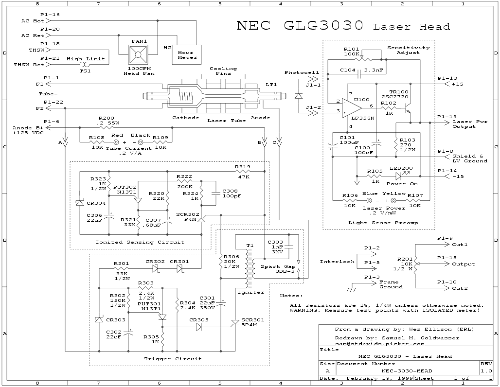
Complete Ar/Kr Ion Laser Power Supply Schematics
The circuit is divided into two sections: the isolated external loop connected to the remote interface connector on the front of the power supply unit (PSU) and the non-isolated inner loop connected to the high-tension (AC line) supply. The two...
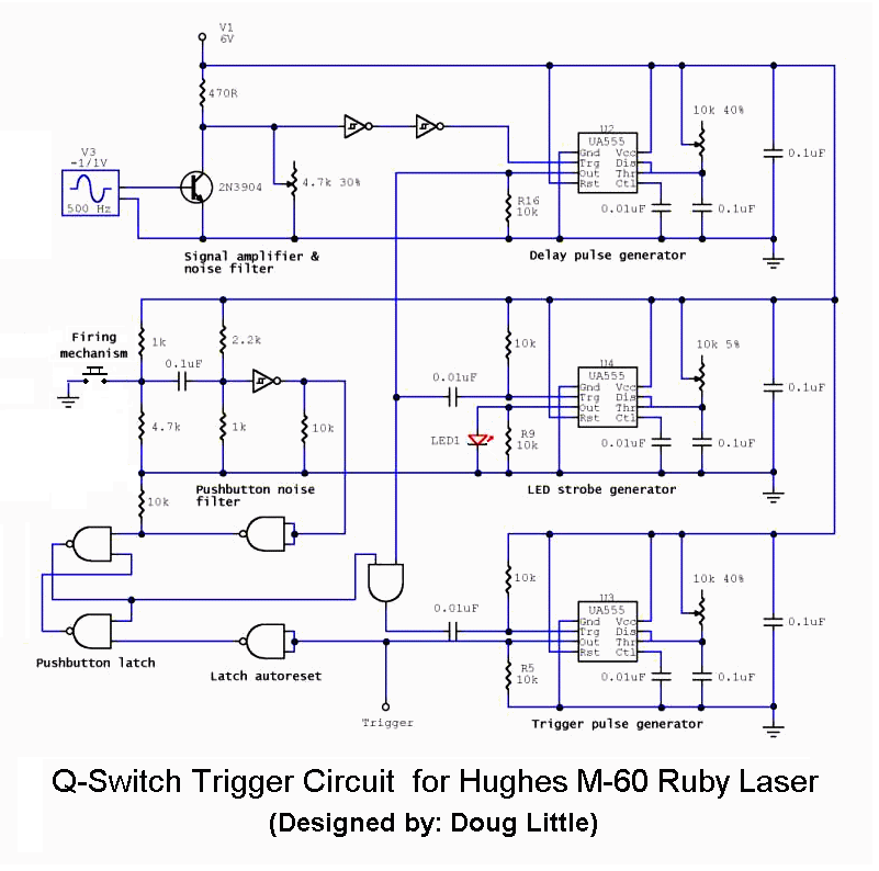
Complete SS Laser Power Supply Schematics
This chapter contains circuit diagrams for several power supplies for pulsed solid-state lasers. These include units suitable for driving the popular Hughes ruby and YAG rangefinder laser assemblies, one utilizing the flash from a disposable pocket camera, and a high-energy...
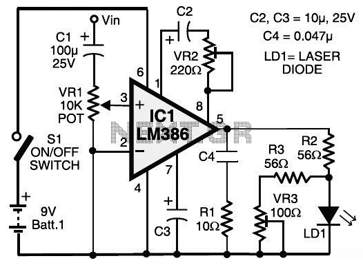
Laser Communication (Transmitter & Receiver)
This circuit diagram represents a laser communication system that transmits sound or music signals using a laser beam. The intensity of the laser beam varies in accordance with the amplitude of the sound signal. The variation in the intensity of...
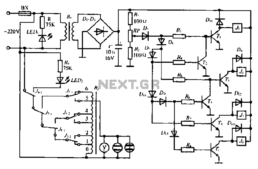
An automatic voltage regulator circuit
A step-down transformer converts AC 220V to a lower voltage. A diode bridge rectifier and filter capacitor provide a direct current (DC) output, which fluctuates with variations in the grid voltage. A resistive voltage divider is used for sampling. When...
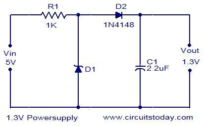
1.3V Power supply
This 1.3V power supply can serve as a replacement for the 1.3V Mercury Cell in any circuit. When a 5V input is applied to the circuit, the voltage drop across the Zener diode D1 will be approximately 2V. The diode...
disassembled key chain laser
A new user expresses interest in lasers and has purchased an inexpensive red laser pointer and LED light combination keychain.
The red laser pointer and LED light combination keychain is a compact and versatile device that serves multiple functions. The red...