


Hacking Hex Bug Spiders
#hexapod
#infra-red
#remote control
#robot
#hacking
#smart cities
#agent based simulation
#hex bug spiders
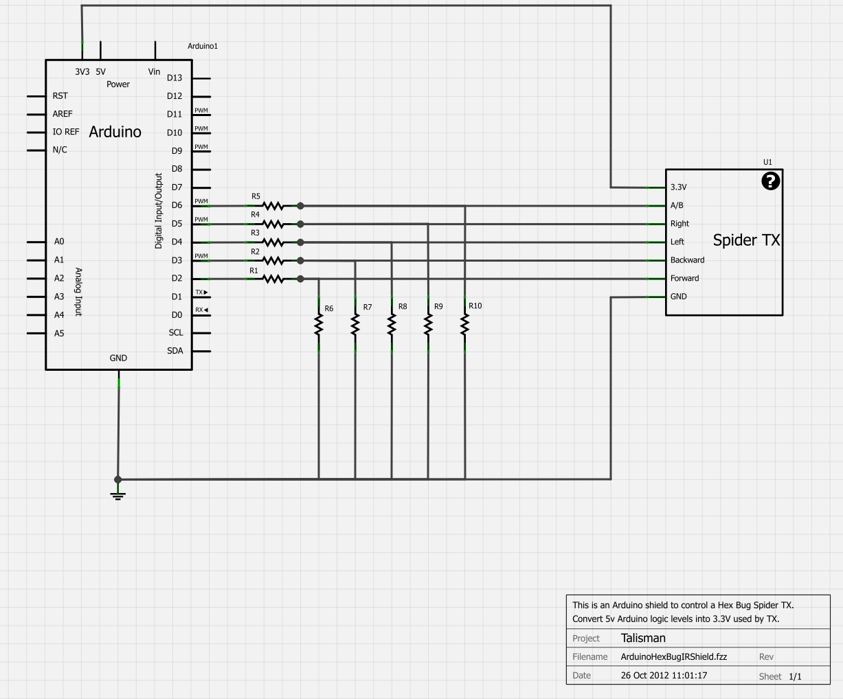
Description: For the Smart Cities exhibition in Leeds in a couple of weeks, a physical representation of an agent-based simulation is being developed. Hex Bug Spiders are inexpensive hexapod robots controlled via an infra-red transmitter with an A or B code, allowing simultaneous control of two units. Their walking mechanism is known as the Jamius walking mechanism, named after its inventor. Upon disassembly, the construction of the Hex Bug reveals a surprisingly robust design for a low-cost toy. Both the handheld transmitter and the robot's receiver utilize the AT8EB microcontroller from Alpha Microelectronics Corp, while the robot incorporates an ST1155A H-Bridge driver. Although many blogs discuss hacking these spiders, it was determined that replacing the electronics is more practical than modifying the surface mount board. Out of three spiders, two remain intact while one has been disassembled. The intent is to modify the IR transmitter to control two spiders using an Arduino connected to a computer, while adding a ZigBee radio for wireless control to the third spider.
Upon examining the transmitter PCB, exposed test points for the forward, backward, left, and right switches were identified, allowing for easy wire attachment. The A/B switch was also accessible for soldering, but the battery terminals were covered in hot melt glue, complicating access. Seven wires were successfully attached to the PCB and routed through the A/B switch hole before reassembly. The functions of the test points were labeled as GND, Forward, +3.3V, Backward, with the A/B code located below the left function, and Right. Although some individuals connect Arduinos directly to the transmitter inputs, a potential divider was employed to prevent the 5V logic of the Arduino from interfacing directly with the 3.3V logic of the AT8EB microcontroller. This setup was integrated into an Arduino shield, with the modified transmitter affixed to a strip board using hot melt glue, enabling control of two spiders via an Arduino connected to a laptop. The laptop runs a Java program that communicates with the Arduino through a USB connection, issuing single-character commands to dictate the robot's state—forward, backward, rotate left, rotate right, or stop—for both spiders based on the A/B code.
A one-second delay is necessary after establishing the serial port connection before sending commands to avoid command loss. While this multiplexing method allows control of two spiders from a single transmitter, it is suggested that two HexBug Arduino shields would enhance functionality. Through experimentation, it was determined that maintaining the TX pins in spider A's state for 80 ms, followed by a similar duration for spider B, yields reliable simultaneous control. As the project has progressed to utilize a webcam for spider positioning, issues have arisen with A/B code multiplexing. The next phase will focus on enabling the spider to follow a colored marker, which requires disabling the A/B code multiplexing on the Arduino for improved reliability.
The project exemplifies the integration of microcontroller technology, robotics, and software programming, showcasing a practical application of electronics in creating interactive and responsive robotic systems. The approach of modifying existing consumer electronics for educational and experimental purposes highlights the versatility and potential for innovation within the field of electronics engineering.For the Smart Cities exhibition in Leeds in a couple of weeks, we`ve been building a physical representation of an agent based simulation. Hex Bug Spiders are relatively cheap hexapod robots that are controlled via an infra-red transmitter which has an A or B code so that you can control two simultaneously.
The way it walks is referred to as the J amius walking mechanism after its inventor (see: ). After taking the Hex Bug apart the construction is actually really good for a cheap toy. Both the hand held transmitter and the receiver in the robot are based around the AT8EB one chip microcontroller (Alpha Microelectronics Corp), with the robot itself also containing an ST1155A H Bridge driver. I`ve seen a lot of blog posts about hacking these spiders, but after trying to modify the robot`s control PCB to attach wires to the H Bridge driver directly (as in this blog post: ), I`ve decided that it`s easier to replace all the electronics rather than hack the surface mount board.
Out of the three spiders that I have, I`ve left two robots untouched while the third one has been disassembled. The logic behind this is to modify the IR transmitter and control two via an Arduino attached to a computer, while adding a ZigBee radio to the third for wireless control.
After examining the transmitter PCB, I noticed that there are exposed test points which can be used to attach wires for the forward, backward, left and right switches. I then discovered the following blog post doing almost exactly the same thing: The four test points for the forward, backward, left and right buttons are exposed, so it`s easy to solder on to them.
I did have to very carefully remove some of the tape covering the button clickers first though. The A/B switch is very easy to solder to, but the + and terminals from the battery are covered in hot melt glue which was very difficult to cut away. Then I had seven wires attached to the PCB which I routed through the A/B switch hole on the front case and re-assembled the transmitter.
Reading from left to right, the white arrows identify the functions as follows: GND, Forward, +3. 3V, Backward, (A/B code bottom with left above it), Right. I have seen people connect Arduinos directly to the inputs of these transmitters, but, as I wasn`t happy connecting the 5v logic of the Arduino to the 3. 3v logic of the AM8EB microprocessor, I used potential dividers on all the inputs. It`s never a good idea in microelectronics to have an input pin higher than Vss even if there are protection Zeners on the inputs.
I have built this into an Arduino shield with the modified transmitter stuck onto the strip board using hot melt glue. This allows me to control two spiders via an Arduino connected via USB to a laptop. The laptop is running a Java program which uses the USB connection as a serial port to send single character commands to the Arduino which set the robot state as forward, backward, rotate left, rotate right or stop for two spiders (via the A/B code).
What I`ve found is that there needs to be about a 1 second delay after bringing up the serial port before you start sending commands to the robots, otherwise you lose the commands. While this does work to control two spiders from one transmitter using multiplexing on the Arduino to flip between the A and B codes, I think you really need two HexBug Arduino shields for it to work.
By trial and error I found that holding the TX pins in spider A`s state for 80 ms, followed by the same for spider B, gave fairly reliable control of both simultaneously. Now that the project has progressed beyond the initial stages and we`re using a webcam to position the spider, this A/B code multiplexing is causing a lot of problems.
The next phase involves getting the spider to follow a coloured marker and the only way I could get this to work reliably was to disable the A/B code multiplexing on the Arduino.
Upon examining the transmitter PCB, exposed test points for the forward, backward, left, and right switches were identified, allowing for easy wire attachment. The A/B switch was also accessible for soldering, but the battery terminals were covered in hot melt glue, complicating access. Seven wires were successfully attached to the PCB and routed through the A/B switch hole before reassembly. The functions of the test points were labeled as GND, Forward, +3.3V, Backward, with the A/B code located below the left function, and Right. Although some individuals connect Arduinos directly to the transmitter inputs, a potential divider was employed to prevent the 5V logic of the Arduino from interfacing directly with the 3.3V logic of the AT8EB microcontroller. This setup was integrated into an Arduino shield, with the modified transmitter affixed to a strip board using hot melt glue, enabling control of two spiders via an Arduino connected to a laptop. The laptop runs a Java program that communicates with the Arduino through a USB connection, issuing single-character commands to dictate the robot's state—forward, backward, rotate left, rotate right, or stop—for both spiders based on the A/B code.
A one-second delay is necessary after establishing the serial port connection before sending commands to avoid command loss. While this multiplexing method allows control of two spiders from a single transmitter, it is suggested that two HexBug Arduino shields would enhance functionality. Through experimentation, it was determined that maintaining the TX pins in spider A's state for 80 ms, followed by a similar duration for spider B, yields reliable simultaneous control. As the project has progressed to utilize a webcam for spider positioning, issues have arisen with A/B code multiplexing. The next phase will focus on enabling the spider to follow a colored marker, which requires disabling the A/B code multiplexing on the Arduino for improved reliability.
The project exemplifies the integration of microcontroller technology, robotics, and software programming, showcasing a practical application of electronics in creating interactive and responsive robotic systems. The approach of modifying existing consumer electronics for educational and experimental purposes highlights the versatility and potential for innovation within the field of electronics engineering.For the Smart Cities exhibition in Leeds in a couple of weeks, we`ve been building a physical representation of an agent based simulation. Hex Bug Spiders are relatively cheap hexapod robots that are controlled via an infra-red transmitter which has an A or B code so that you can control two simultaneously.
The way it walks is referred to as the J amius walking mechanism after its inventor (see: ). After taking the Hex Bug apart the construction is actually really good for a cheap toy. Both the hand held transmitter and the receiver in the robot are based around the AT8EB one chip microcontroller (Alpha Microelectronics Corp), with the robot itself also containing an ST1155A H Bridge driver. I`ve seen a lot of blog posts about hacking these spiders, but after trying to modify the robot`s control PCB to attach wires to the H Bridge driver directly (as in this blog post: ), I`ve decided that it`s easier to replace all the electronics rather than hack the surface mount board.
Out of the three spiders that I have, I`ve left two robots untouched while the third one has been disassembled. The logic behind this is to modify the IR transmitter and control two via an Arduino attached to a computer, while adding a ZigBee radio to the third for wireless control.
After examining the transmitter PCB, I noticed that there are exposed test points which can be used to attach wires for the forward, backward, left and right switches. I then discovered the following blog post doing almost exactly the same thing: The four test points for the forward, backward, left and right buttons are exposed, so it`s easy to solder on to them.
I did have to very carefully remove some of the tape covering the button clickers first though. The A/B switch is very easy to solder to, but the + and terminals from the battery are covered in hot melt glue which was very difficult to cut away. Then I had seven wires attached to the PCB which I routed through the A/B switch hole on the front case and re-assembled the transmitter.
Reading from left to right, the white arrows identify the functions as follows: GND, Forward, +3. 3V, Backward, (A/B code bottom with left above it), Right. I have seen people connect Arduinos directly to the inputs of these transmitters, but, as I wasn`t happy connecting the 5v logic of the Arduino to the 3. 3v logic of the AM8EB microprocessor, I used potential dividers on all the inputs. It`s never a good idea in microelectronics to have an input pin higher than Vss even if there are protection Zeners on the inputs.
I have built this into an Arduino shield with the modified transmitter stuck onto the strip board using hot melt glue. This allows me to control two spiders via an Arduino connected via USB to a laptop. The laptop is running a Java program which uses the USB connection as a serial port to send single character commands to the Arduino which set the robot state as forward, backward, rotate left, rotate right or stop for two spiders (via the A/B code).
What I`ve found is that there needs to be about a 1 second delay after bringing up the serial port before you start sending commands to the robots, otherwise you lose the commands. While this does work to control two spiders from one transmitter using multiplexing on the Arduino to flip between the A and B codes, I think you really need two HexBug Arduino shields for it to work.
By trial and error I found that holding the TX pins in spider A`s state for 80 ms, followed by the same for spider B, gave fairly reliable control of both simultaneously. Now that the project has progressed beyond the initial stages and we`re using a webcam to position the spider, this A/B code multiplexing is causing a lot of problems.
The next phase involves getting the spider to follow a coloured marker and the only way I could get this to work reliably was to disable the A/B code multiplexing on the Arduino.
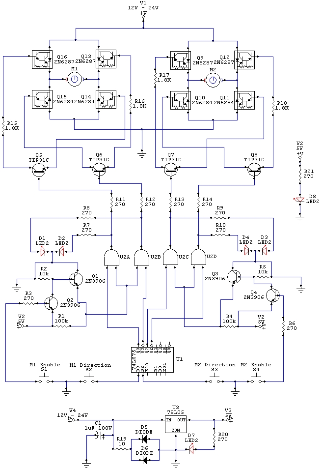
Electronic robot wiring schematic
The wiring schematic played a significant role in the robot. This diagram is used to graphically display all the wiring of the motor-controlling micro-components that enabled the robot to physically move forward, backward, left, right, and stop. This diagram was...
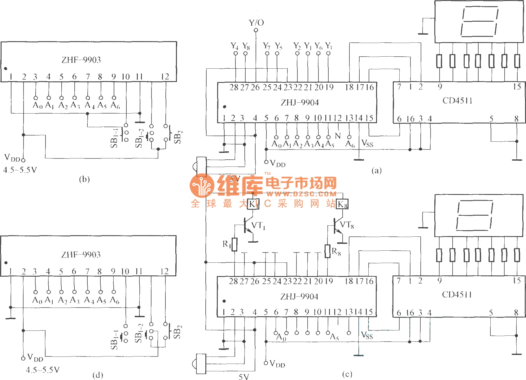
The eight-way remote control circuit diagram composed of module
This is an eight-way signal remote control selection circuit composed of ZHJ-9904. It includes a remote control transmitter circuit, an eight-way switch control circuit, and a remote control transmitter.
The eight-way signal remote control selection circuit utilizing the ZHJ-9904 is designed...
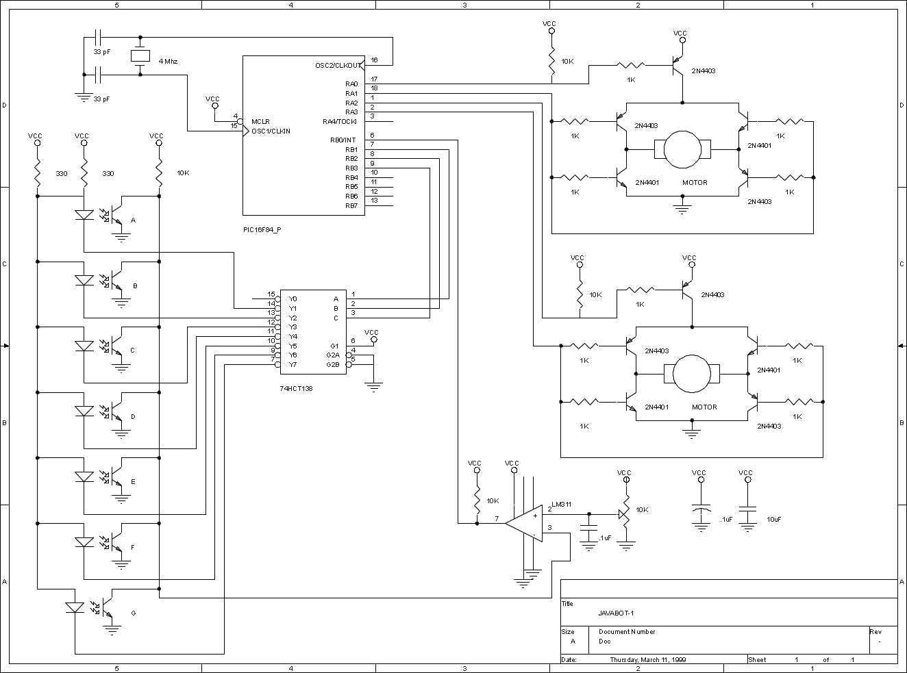
JavaBot1
The JavaBot1 is a small line following robot designed to follow a black line drawn on a dry erase board. It is designed to follow very tight curves. The software still has lots of room for improvement but works well...

A simple remote control switch circuit
The ML4423 is an integrated controller designed for single-phase and two-phase AC induction motors. It features PWM (Pulse Width Modulation) capabilities for speed control and includes various protection circuits such as short circuit protection, fire protection, and a reference power...

Ophthalmology light lamp switch circuit
This is a remote-controlled light switch circuit that can be used for remote control toys, flashlight operation, or laser pointers. When the light from a torch illuminates the photosensitive resistor RL2, its resistance decreases, causing transistor VT2 to turn on...
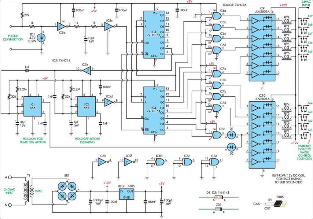
Inexpensive Remote Watering System
This remotely controlled watering system is both inexpensive and easy to expand. It is designed to operate in conjunction with a conventional watering timer.
The remotely controlled watering system is an innovative solution for automated irrigation, allowing users to manage watering...
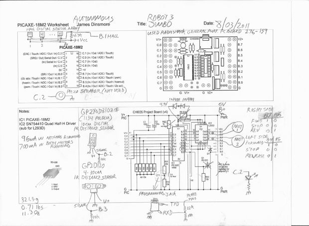
Robot Autonomous Sensor Platform
This is an autonomous robot designed to explore the interfacing of various sensors with a PICAXE processor. Its mission is to search for a magnet.
The autonomous robot operates based on a microcontroller architecture centered around the PICAXE processor, which is...
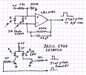
Homemade Robots polymax improvements
The 2009 Robot Rally highlighted the flaws resulting from a rapid three-week engineering and building project. Time-saving shortcuts in both code and hardware led to multiple failures, including edge detectors, beacon trackers, and line follower reversals. Investigations were conducted into...
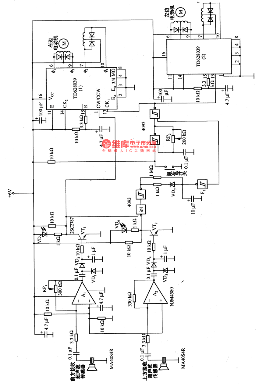
Remote control robot circuit
The remote control robot circuit is illustrated in the accompanying figure. Figure 2-36(a) presents the circuit diagram, while figure 2-36(b) depicts the operating timing diagram. The robot's rotation process involves an ultrasonic launching circuit, which consists of a 40 kHz...