


Speech Circuit Controlling the Robot
#speech control
#robot
#datasheet
#address lines
#RAM chip
#enable pin
#circuit troubleshooting
#hardware modification
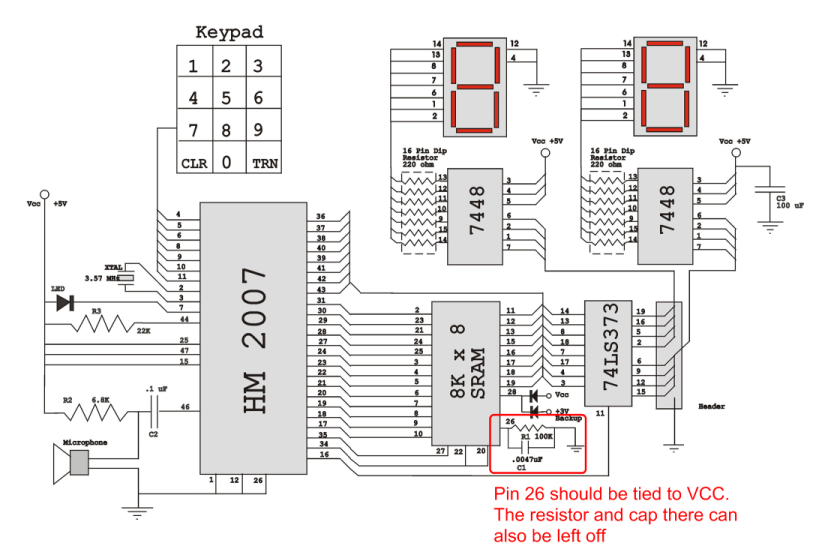
Description: Verify the pin configurations on the datasheets for the integrated circuits used in your project, making necessary adjustments. In this instance, the RAM chip utilized had a non-inverted enable signal on pin 26, while the schematic assumed it was inverted. This discrepancy led to circuit malfunction until it was addressed. Additionally, it is acceptable to rearrange the address lines, which may be jumbled in the schematic to accommodate the PCB design from Images Co. Aligning address lines SA0-A0 from the HM2007 to the RAM and data lines D0-D0 similarly did not present any issues, resulting in a functional setup that is easier to prototype on a breadboard. Unfortunately, assistance cannot be provided for specific modes on the chip as they were not selected. However, relevant information can be found in the Images Co datasheet addendum, as well as on the Talking Toaster page and the HM2007 wiki, which is a valuable resource for interfacing with Arduino. Redrawing the schematic from the ground up is advisable, utilizing address lines SA0-A0 and data lines D0-D0 as indicated in the schematic. It may be beneficial to seek help from a professor or teacher for this task. If the project continues to malfunction despite efforts, it is possible that the RAM chip or HM2007 is defective. Although this is not the most common issue, a faulty HM2007 chip or RAM chip has been encountered. The most prudent course of action would be to order replacement chips, with previous orders from Images Co incurring approximately $60 in shipping costs.
The circuit design involves several critical components, including the RAM chip, HM2007, and address and data lines. The RAM chip's pin configuration is essential for ensuring proper functionality, particularly regarding the enable signal. In this case, the enable signal's inversion must be correctly interpreted in the schematic to avoid operational failures.
When designing the schematic, it is crucial to maintain the integrity of the address and data lines. The alignment of SA0-A0 and D0-D0 must be consistent across both the HM2007 and the RAM chip to ensure seamless communication between them. This alignment facilitates the flow of data and control signals, which is vital for the circuit's operation.
For the schematic layout, it is recommended to use a software tool that allows for precise placement of components and wiring. The schematic should clearly represent the connections between the HM2007 and the RAM chip, including all necessary power and ground connections.
In the event that circuit issues persist, a systematic troubleshooting approach should be adopted. This includes verifying all connections, checking for shorts or opens in the circuit, and testing the functionality of individual components. If the components are suspected to be defective, replacement chips should be procured from a reliable supplier to ensure project continuity.
Overall, attention to detail in the schematic design, thorough testing, and proper component selection will significantly enhance the likelihood of successful project completion.Triple check your pins on the datasheets for your chips and make changes if you need to. In my case, The RAM chip I used had a non-inverted enable on pin26, but the schematic assumed the enable was inverted. This caused the circuit not to work until I figured it out. Also, feel free to move the address lines around. These lines are mixed up on the schematic only to facilitate the PCB designed from Images co. Aligning SA0-A0 from the HM2007 to RAM and D0-D0 in the same fashion caused no problems for me. It works great and is easier to build on a breadboard. Soln. I am sorry that I cannot help in these cases at all as I did not choose to use this mode on the chip. However, there is some information in the Images Co datasheet Addendum and some more info on the talking toaster page as well as some info for interfacing the Arduino.
(< that last link is the HM2007 wiki, great resource. ) 4. ) Redo the schematic from scratch (not as hard as you might think!) Use address lines SA0-A0 and data lines D0-D0 like in this schematic. Draw your own schematic. You may need to enlist the help of a professor or teacher to help you with this. 5. ) If nothing you do is fixing your project, it is very likely that your RAM chip or HM2007 is bad. This is not the most likely problem, however, I did encounter a bad HM2007 chip and a bad RAM chip. The best bet here is to order new chips. I made several orders from Images Co and was charges overall about $60 for shipping on everything.
The circuit design involves several critical components, including the RAM chip, HM2007, and address and data lines. The RAM chip's pin configuration is essential for ensuring proper functionality, particularly regarding the enable signal. In this case, the enable signal's inversion must be correctly interpreted in the schematic to avoid operational failures.
When designing the schematic, it is crucial to maintain the integrity of the address and data lines. The alignment of SA0-A0 and D0-D0 must be consistent across both the HM2007 and the RAM chip to ensure seamless communication between them. This alignment facilitates the flow of data and control signals, which is vital for the circuit's operation.
For the schematic layout, it is recommended to use a software tool that allows for precise placement of components and wiring. The schematic should clearly represent the connections between the HM2007 and the RAM chip, including all necessary power and ground connections.
In the event that circuit issues persist, a systematic troubleshooting approach should be adopted. This includes verifying all connections, checking for shorts or opens in the circuit, and testing the functionality of individual components. If the components are suspected to be defective, replacement chips should be procured from a reliable supplier to ensure project continuity.
Overall, attention to detail in the schematic design, thorough testing, and proper component selection will significantly enhance the likelihood of successful project completion.Triple check your pins on the datasheets for your chips and make changes if you need to. In my case, The RAM chip I used had a non-inverted enable on pin26, but the schematic assumed the enable was inverted. This caused the circuit not to work until I figured it out. Also, feel free to move the address lines around. These lines are mixed up on the schematic only to facilitate the PCB designed from Images co. Aligning SA0-A0 from the HM2007 to RAM and D0-D0 in the same fashion caused no problems for me. It works great and is easier to build on a breadboard. Soln. I am sorry that I cannot help in these cases at all as I did not choose to use this mode on the chip. However, there is some information in the Images Co datasheet Addendum and some more info on the talking toaster page as well as some info for interfacing the Arduino.
(< that last link is the HM2007 wiki, great resource. ) 4. ) Redo the schematic from scratch (not as hard as you might think!) Use address lines SA0-A0 and data lines D0-D0 like in this schematic. Draw your own schematic. You may need to enlist the help of a professor or teacher to help you with this. 5. ) If nothing you do is fixing your project, it is very likely that your RAM chip or HM2007 is bad. This is not the most likely problem, however, I did encounter a bad HM2007 chip and a bad RAM chip. The best bet here is to order new chips. I made several orders from Images Co and was charges overall about $60 for shipping on everything.
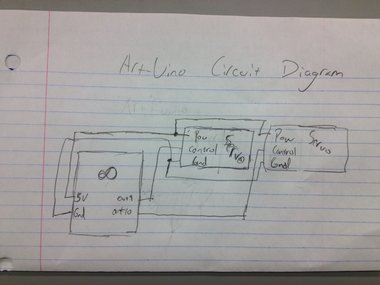
Human-Computer Interface Technology 3
This week, there was a Southern theme in anticipation of Spring Break, leading to the decision to build a LassoBot. This robot throws a lasso in a circular motion until it captures an object in its path. Once an object...
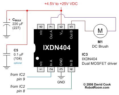
Simple Robot That Drives Forward and Back
The Flip-Flop Robot drives forward until it encounters an obstacle, at which point it reverses until it strikes another obstacle. This back-and-forth motion continues indefinitely. By simplifying the functionality to this basic behavior, the robot can be constructed using an...
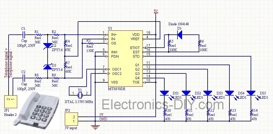
Cellphone Operated Land Rover (Mobile Phone Controlled Robot)
Cellphone Operated Land Rover (Mobile Phone Operated Robot). In this project, the robot is controlled by a mobile phone that makes a call to the mobile phone attached to the robot.
The cellphone operated Land Rover project involves the design and...
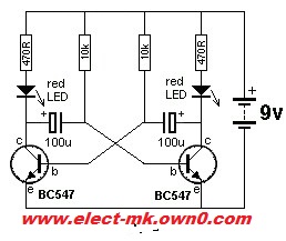
Robot eyes circuit
Robot eyes circuit of Service. A simple circuit to simulate a man appointed to it. It consists of a dual-lamp working in an unsteady manner. Circuit diagram.
The robot eyes circuit is designed to create a visual effect that simulates the...
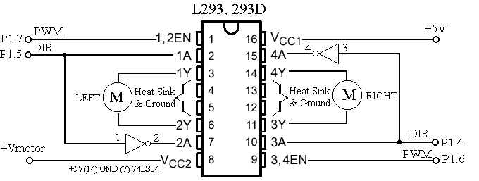
de amst wiskar: robot line folower
One of the students has created a robot that utilizes two stepper motors and a simple IR sensor. The robot, which is depicted in the accompanying image, has some issues such as a lack of battery support and misalignment of...
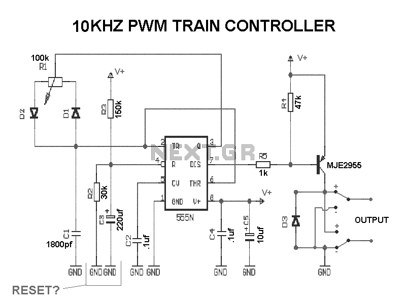
Dancing Robots
A robot that dances to music. It would be fascinating to have a small robot on your desk dancing to music from Fatboy Slim. Winamp provides an API for writing music visualization plug-ins. A plug-in was developed that sends signals...
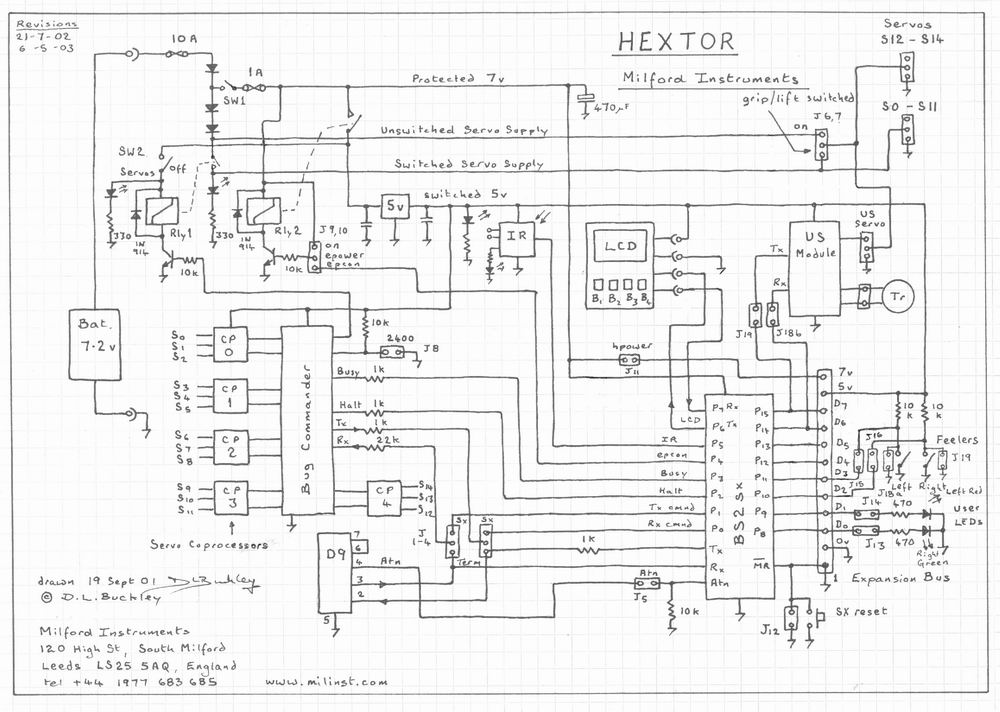
Hextor Hexapod Robot
The circuit includes multiple connections for a BOS (Basic Operating System) processor. It has a serial connection for transmitting data to the BOS processor (pin 0) and receiving data from it (pin 1). Pin 2 is used to supply power...
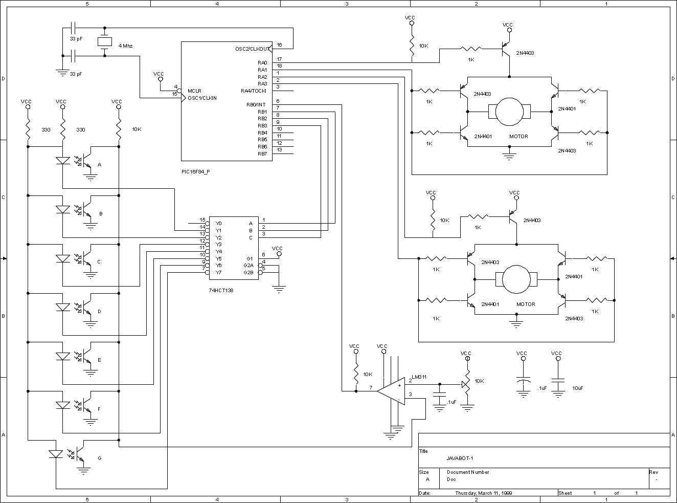
JavaBot1
The JavaBot1 is a small line following robot designed to follow a black line drawn on a dry erase board. It is designed to follow very tight curves. The software still has lots of room for improvement but works well...
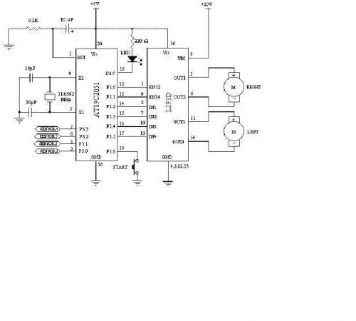
to verify schematics for 2 motor robot
Constructing a robot, or rather a vehicle, that uses two motors. Reference materials regarding the schematics for the circuit design have been obtained, but the current schematics utilize smaller motors that draw less power and operate with a lower power...