


Wiring Diagram for a Back-And-Forth Robot
#Clare IXDI404PI
#motor control
#robot chassis
#back-and-forth
#DIY robot
#schematic
#wiring diagram
#hobby robotics
#autonomous robot
#electronics project
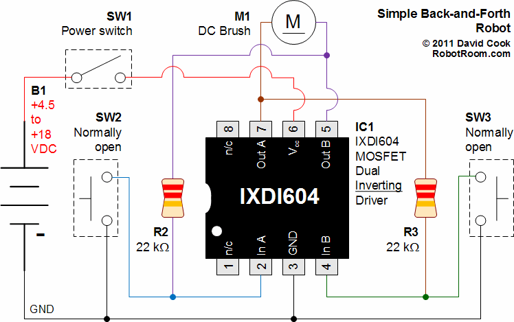
Description: A schematic that illustrates the connections to the Clare IXDI404PI chip, which serves as both the control unit and power driver for a DIY Back-And-Forth robot.
The Clare IXDI404PI chip is a dual-channel, high-speed, high-current driver designed for driving inductive loads such as motors. In the context of a Back-And-Forth robot, this chip plays a crucial role in controlling the movement and direction of the robot's motors, enabling it to move forward and backward in response to control signals.
The schematic typically includes the following components and connections:
1. **Power Supply**: The IXDI404PI requires a stable power supply, often in the range of 4.5V to 15V. Proper decoupling capacitors should be placed close to the power pins of the chip to filter out noise and stabilize the voltage.
2. **Input Control Signals**: The chip accepts input signals from a microcontroller or other control circuitry. These signals determine the operation of the motor drivers. The input pins are typically connected to the output pins of a microcontroller, which can be programmed to send high or low signals based on the desired movement of the robot.
3. **Motor Connections**: The output pins of the IXDI404PI are connected to the motors. Each channel can drive a motor, allowing for independent control of two motors, which is essential for achieving forward and backward movement. The schematic should clearly depict the connection of each motor's terminals to the respective output pins of the chip.
4. **Protection Diodes**: To protect the IXDI404PI from back EMF generated when the motors are turned off, flyback diodes are often included in the schematic. These diodes are connected in parallel with the motors and serve to safely dissipate voltage spikes.
5. **Ground Connections**: A common ground should be established for the power supply, the IXDI404PI, and the microcontroller to ensure that all components operate correctly and to minimize potential differences that could lead to erratic behavior.
6. **Additional Components**: Depending on the design, additional components such as resistors, capacitors, and possibly additional logic gates may be included to condition the input signals or to provide feedback for more sophisticated control schemes.
The schematic serves as a vital reference for assembling the Back-And-Forth robot, ensuring that all connections are made correctly to facilitate reliable operation of the motors through the IXDI404PI chip. Proper layout and routing of the connections are critical for minimizing interference and ensuring the longevity of the components involved.A schematic that details the connections to the Clare IXDI404PI chip that is both the brains and the brawn of the Back-And-Forth robot that you can make yourself..
The Clare IXDI404PI chip is a dual-channel, high-speed, high-current driver designed for driving inductive loads such as motors. In the context of a Back-And-Forth robot, this chip plays a crucial role in controlling the movement and direction of the robot's motors, enabling it to move forward and backward in response to control signals.
The schematic typically includes the following components and connections:
1. **Power Supply**: The IXDI404PI requires a stable power supply, often in the range of 4.5V to 15V. Proper decoupling capacitors should be placed close to the power pins of the chip to filter out noise and stabilize the voltage.
2. **Input Control Signals**: The chip accepts input signals from a microcontroller or other control circuitry. These signals determine the operation of the motor drivers. The input pins are typically connected to the output pins of a microcontroller, which can be programmed to send high or low signals based on the desired movement of the robot.
3. **Motor Connections**: The output pins of the IXDI404PI are connected to the motors. Each channel can drive a motor, allowing for independent control of two motors, which is essential for achieving forward and backward movement. The schematic should clearly depict the connection of each motor's terminals to the respective output pins of the chip.
4. **Protection Diodes**: To protect the IXDI404PI from back EMF generated when the motors are turned off, flyback diodes are often included in the schematic. These diodes are connected in parallel with the motors and serve to safely dissipate voltage spikes.
5. **Ground Connections**: A common ground should be established for the power supply, the IXDI404PI, and the microcontroller to ensure that all components operate correctly and to minimize potential differences that could lead to erratic behavior.
6. **Additional Components**: Depending on the design, additional components such as resistors, capacitors, and possibly additional logic gates may be included to condition the input signals or to provide feedback for more sophisticated control schemes.
The schematic serves as a vital reference for assembling the Back-And-Forth robot, ensuring that all connections are made correctly to facilitate reliable operation of the motors through the IXDI404PI chip. Proper layout and routing of the connections are critical for minimizing interference and ensuring the longevity of the components involved.A schematic that details the connections to the Clare IXDI404PI chip that is both the brains and the brawn of the Back-And-Forth robot that you can make yourself..
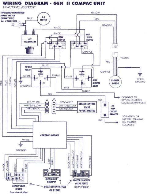
ANTIQUE CAR DIAGRAM WIRING
Mercury, Oldsmobile, Plymouth, Pontiac, muscle cars, and antique classic car wiring diagrams are continuously being added to this site. The wiring diagram for the Porsche 911L engine from the 1968 model has undergone changes since the original scheme. For those...
Light circuit diagram: 1996 Ford Windstar Wiring Diagram
The section of the 1996 Ford Windstar wiring diagram includes details on power distribution, common connections, rear circuits, ignition systems, the fuse panel, battery connections, instrument illumination, radio wiring, left rear speaker connections, remote headphone module, solid-state components, and right...
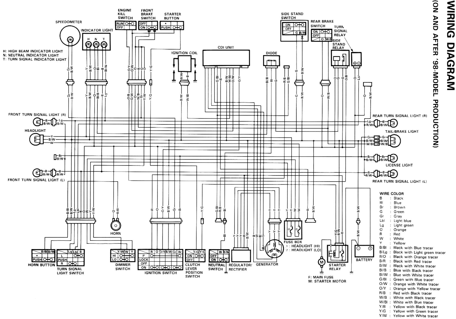
1998 DR-650 Suzuki Wiring Diagram Off-road Bike
The DR-650 wiring diagram pertains to the Suzuki DR-650, a single-cylinder, dual-sport motorcycle. This wiring diagram includes a color code for the wires. The schematic diagram provides complete connections for various components, such as the speedometer, lights, CDI unit, and...
motor timer
The primary concept is to rotate the motor slightly every 15 seconds. A monofilament line conveys the motion to the ornament, which is wound by the motor and gradually unwinds as the ornament turns. The charging circuit includes a 1...
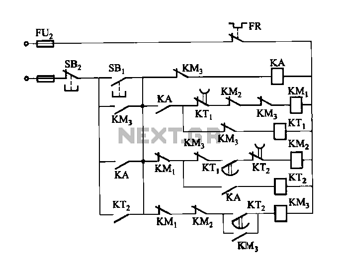
2 -Y- connection automatic three-speed motor acceleration control circuit
Figure 3-118 illustrates an automatic acceleration control circuit. This circuit employs a male contactor time relay, enabling the motor to start automatically at a low speed before transitioning to high-speed operation.
The automatic acceleration control circuit depicted in Figure 3-118 is...
2000 Chevrolet Chevy Blazer Wiring Diagram
The part of the 2000 Chevrolet Chevy Blazer wiring diagram includes a power distribution schematic, fuel pump relay control, fuel pump and sender, splice pack, fuel pump prime connector, ground distribution schematic, underhood fuse block, and vehicle control module.
The wiring...
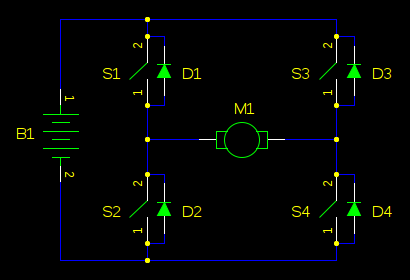
boost Why should I worry about a motor causing my supply voltage to shoot up when the back-EMF cant exceed the supply voltage
In motor control circuits, precautions must be taken to prevent the motor from feeding back into the power supply, which can cause the supply voltage to rise and potentially damage components. However, unless an external force is accelerating the motor,...
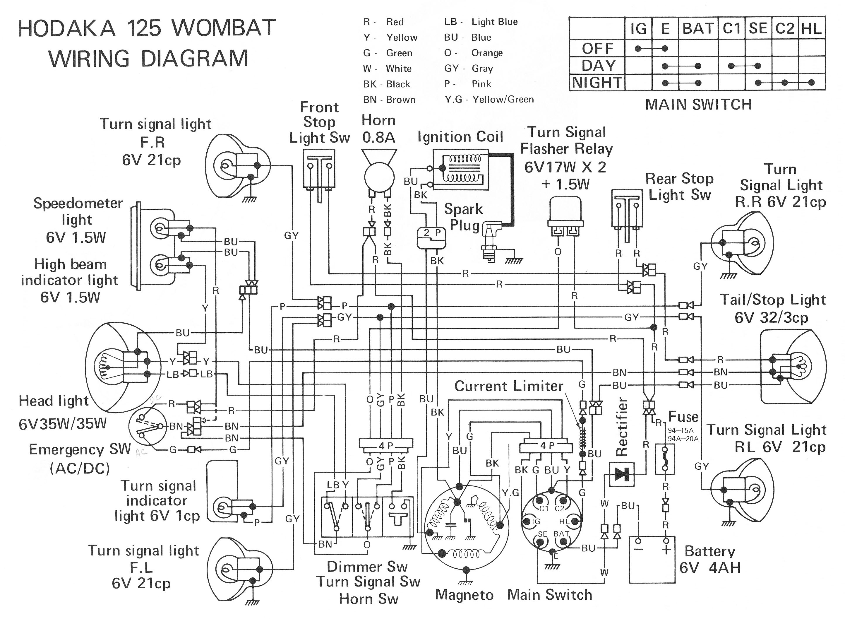
ELECTRONIC SCHEMATIC CIRCUIT DIAGRAMS
Electronic Schematic Circuit Diagrams Manual PDF Download.
The document provides a comprehensive manual that focuses on electronic schematic circuit diagrams. These diagrams are essential tools for understanding and designing electronic circuits, offering visual representations of circuit components and their interconnections. The...
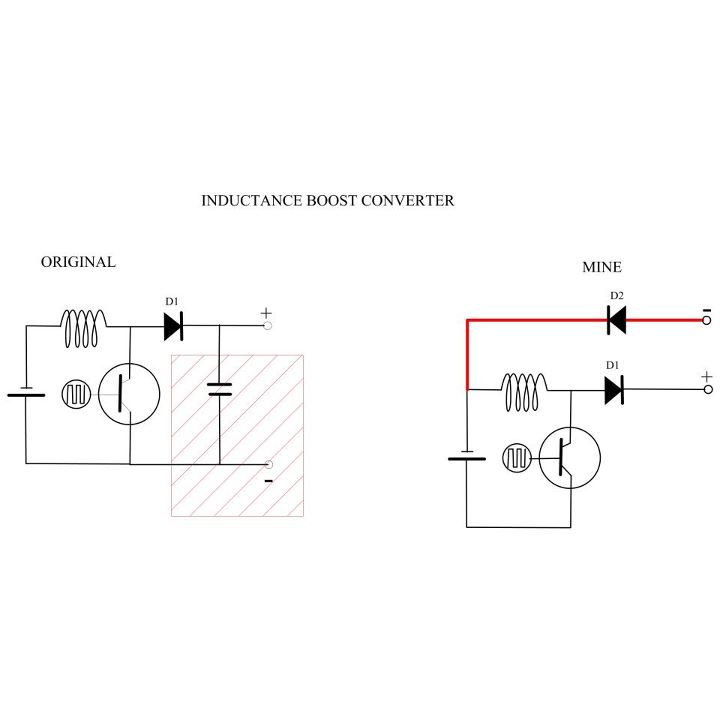
My Motors got me to Tap into Radiant Energy
A new user is seeking to share information about their experiences on this platform.
The user expresses a desire to communicate and engage with the community regarding their experiences. This indicates an interest in exchanging knowledge and possibly seeking assistance or...