


5-channel low-power interface circuit programmable sensor signal processor AD7714 and DSP
#ADSP-2103
#ADSP-2105
#AD7714
#digital signal processor
#interface circuit
#programmable sensor
#signal processing
#low-power
#measurement
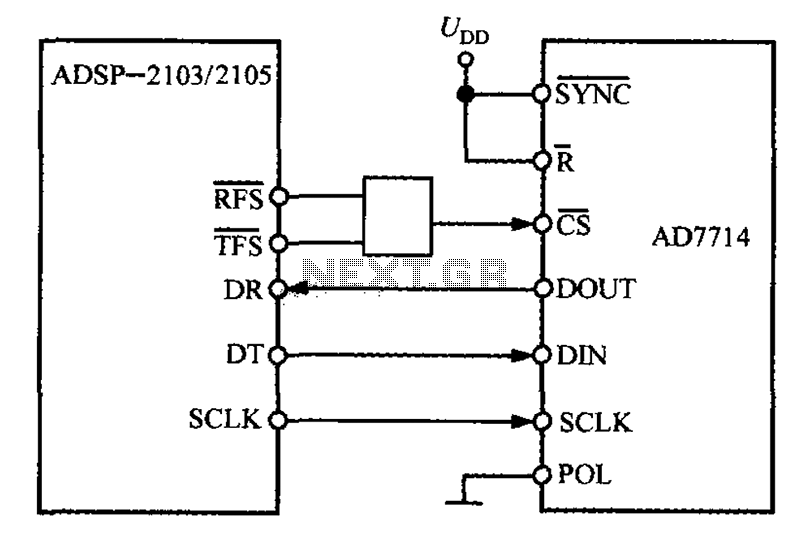
Description: The ADSP-2103 and ADSP-2105 are digital signal processors that interface with the AD7714. When the output is active, the ADSP-2103/2105 configuration includes the RFS non-TES non-terminal set to a low level, while the SCLK terminal is configured for serial clock output. The AD7714 operates with a low level of POL termination. To ensure proper functionality of the AD7714, the serial clock frequency of the ADSP-2103/2105 must be limited to less than 3 MHz.
The ADSP-2103 and ADSP-2105 digital signal processors are designed for high-performance signal processing applications. These processors are capable of executing complex algorithms efficiently, making them suitable for various applications such as audio processing, telecommunications, and control systems.
The interface circuit with the AD7714 is critical for ensuring seamless communication between the digital signal processor and the analog-to-digital converter (ADC). The configuration of the RFS (Receive Frame Sync) non-TES (non-terminal) to a low level indicates that the processor is ready to receive data, which is essential for synchronized data transfer.
The SCLK (Serial Clock) terminal, configured for serial clock output, serves as the timing reference for data transmission between the ADSP-2103/2105 and the AD7714. It is important to maintain the serial clock frequency below 3 MHz to prevent potential data corruption and ensure reliable operation of the AD7714. Exceeding this frequency can lead to timing issues that may disrupt the ADC's ability to accurately convert analog signals to digital form.
In summary, the integration of the ADSP-2103/2105 with the AD7714 involves careful attention to configuration settings and timing requirements to achieve optimal performance. Proper setup of the RFS and SCLK terminals is crucial for the effective operation of the overall system, facilitating accurate data conversion and processing.ADSP-2103 or ADIs ADSP-2105 is produced by a digital signal processor. AD7714 and the ADSP-2103/2105 interface circuit as shown in FIG. When the output is active ADSP-2103/2105 and the RFS non-TES non-terminal configuration to the low level, the SCLK terminal is configured to serial clock output. AD7714 low level of POL termination. To ensure the AD7714 to work properly, ADSP-2103/2105 serial clock frequency should be limited to less than 3MHz.
The ADSP-2103 and ADSP-2105 digital signal processors are designed for high-performance signal processing applications. These processors are capable of executing complex algorithms efficiently, making them suitable for various applications such as audio processing, telecommunications, and control systems.
The interface circuit with the AD7714 is critical for ensuring seamless communication between the digital signal processor and the analog-to-digital converter (ADC). The configuration of the RFS (Receive Frame Sync) non-TES (non-terminal) to a low level indicates that the processor is ready to receive data, which is essential for synchronized data transfer.
The SCLK (Serial Clock) terminal, configured for serial clock output, serves as the timing reference for data transmission between the ADSP-2103/2105 and the AD7714. It is important to maintain the serial clock frequency below 3 MHz to prevent potential data corruption and ensure reliable operation of the AD7714. Exceeding this frequency can lead to timing issues that may disrupt the ADC's ability to accurately convert analog signals to digital form.
In summary, the integration of the ADSP-2103/2105 with the AD7714 involves careful attention to configuration settings and timing requirements to achieve optimal performance. Proper setup of the RFS and SCLK terminals is crucial for the effective operation of the overall system, facilitating accurate data conversion and processing.ADSP-2103 or ADIs ADSP-2105 is produced by a digital signal processor. AD7714 and the ADSP-2103/2105 interface circuit as shown in FIG. When the output is active ADSP-2103/2105 and the RFS non-TES non-terminal configuration to the low level, the SCLK terminal is configured to serial clock output. AD7714 low level of POL termination. To ensure the AD7714 to work properly, ADSP-2103/2105 serial clock frequency should be limited to less than 3MHz.
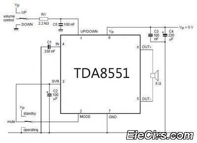
Low-Power Amplifier with digital volume control
An amplifier with digital volume control can be designed predictably due to the simplicity of the circuit, which utilizes a single chip, the TDA8551. This series of mini amplifiers with digital volume control operates as a BTL (Bridge-Tied Load) amplifier...
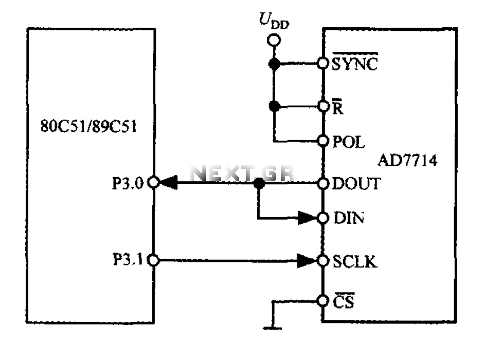
5-channel low-power interface circuit programmable sensor signal processor AD7714 and MCS-51 series microcontroller
The 3-wire interface to the AD7714 can be utilized with various microcontrollers, including microcontrollers and microprocessors. This 3-wire serial interface is particularly suitable for isolation systems, allowing the use of optical couplers. The interface circuit between the AD7714 and the...
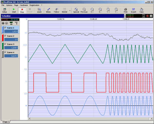
RealView 2.0
RealView is a measurement application, which records and plots measured values from analogue hardware devices in real-time. Several curves can be plotted into a single diagram. Several diagrams can be arranged on one or more pages if necessary. Plot options...
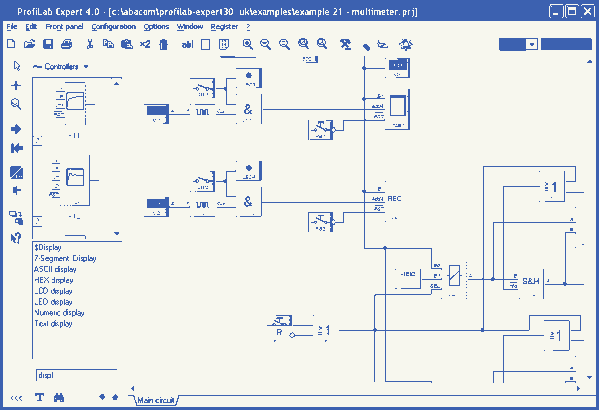
ProfiLab-Expert 4.0
The ProfiLab-Expert software allows you to develop your own digital or analogue measuring technology projects. It doesn't matter if you want to create analogue measurements or digital controls - you can realize it all. And for all this you don't...
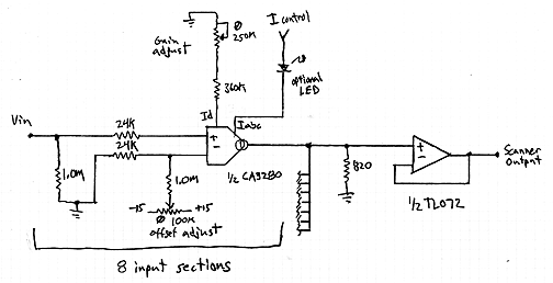
Interpolating Scanner Circuit
This design is for an interpolating scanner, a circuit featuring multiple signal inputs, a control voltage input, and a signal output. The output selectively transitions between inputs, smoothly fading from one to the next as the control voltage increases. A...
5-channel low-power interface circuit programmable sensor signal processor AD7714 and MCS-51 series microcontroller
The 3-wire interface to the AD7714 can be utilized with various microcontrollers, including microcontrollers and microprocessors. This 3-wire serial interface is particularly suitable for isolation systems, allowing the use of optical couplers. The interface circuit between the AD7714 and the...
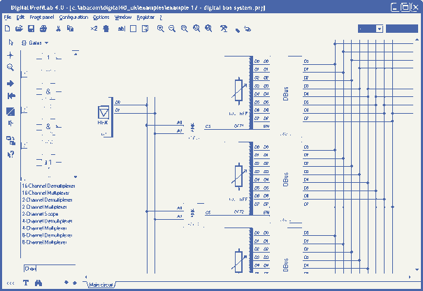
Digital-ProfiLab 4.0
Digital-ProfiLab was designed for measurement and control applications, combining features like circuit and logic simulation, front panel design, and hardware control to one powerful tool. Incoming signals from external devices may be processed and displayed. A circuit editor is used...
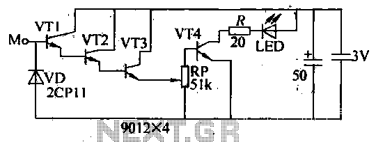
Blanket internal measurement circuit disconnection
The internal disconnection circuit for a blanket operates on the principle of induction. It includes a wire approximately 2 cm in length that senses the proximity of a charged mains power source. When the sensing wire is close to the...
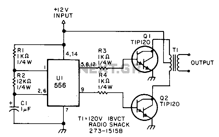
Low-power-inverter
This low-power inverter utilizes only nine components to convert 10 to 16 VDC into a 60 Hz, 115 V square-wave output suitable for operating AC equipment with a maximum power of 25 W. The initial section of the 556 timer...